


© 2024 EasyEDA Some rights reserved ISO/IEC
Editor Version
×
Standard

1.Easy to use and quick to get started
2.The process supports design scales of 300 devices or 1000 pads
3.Supports simple circuit simulation
4.For students, teachers, creators
Profession

1.Brand new interactions and interfaces
2.Smooth support for design sizes of over 5,000 devices or 10,000 pads
3.More rigorous design constraints, more standardized processes
4.For enterprises, more professional users

Ongoing
STD ROV H-Bridge
License: GPL 3.0
Mode: Editors' pick
- 0
Update time:
2020-08-14 13:05:45
Creation time:
2019-05-04 18:00:00
Description
This H-Bridge based Motor controller is meant to controll ROV bilge-pump motors with special attention to low temerature operation and easy integration in other devices over serial communication.
## Heat Management
### Transistor heatsinking
All MOS-FET Transistors are directly soldered onto a heat transferring pad. This Pad conducts the heat to the top-side, where heatsinks can be mounted with thermal glue.
### Powertracks
To reduce the board size, all powertracks on the PCB are 4mm wide. In this configuration they will take 10A with a temperature rise around +40°C above ambient when thermally insulated
(Remember the possible ambient temperature rise due to tracks and Transistors heating the environment).
If higher currents should be driven, fill the tracks with solder to prevent overheating and/or delamination.
### Power-vias
The vias for the powertracks have an extra large drill hole. Filled with solder, this creates a 0.6mm² connection which can take much higher currents than the original vias.
## Onboard controller
The controller used on this board is a ATmega88. Therefore mostly **compatible with standard arduino code**.
### Memory
The ATMega88 is completely pin compatible with the ATMega 48/168. They differ only in regards to memory size and minor features. (Further information listed in the datasheet)
#### ATMega88:
- 8kB self-programmable flash
- 512B EEPROM
- 1kB internal SRAM
#### ATmega168:
- 16kB self-programmable flash
- 512B EEPROM
- 1kB internal SRAM
#### ATMega48:
-4kB self-programmable flash
-256B EEPOM
-512B internal SRAM
### Communication
The board was designed with easy communication in mind. Therefore it features a variety of different communication methods.
#### Serial
The board breaks out two mal communication methods from the µC. The SPI-bus is not completely usable, because the chip-select pin is used to drive a Transistor. The two main Methods of communication are **UART** and **I2C**. Both busses are broken out to one header including power and ground. This allows you to utilize both busses over a single dupond connector.
#### Analog
On the board exists one analog input pad with reference pads next to it. In this way a potentiometer can be directly hooked up to it or you can use any other analog signal (for example generated by a DAC).
The analog reference of the µC will be GND to VCC with 10bit resolution.
#### Custom
For custom communication methods or other general purpose functions, the external interrupt pins are located as testpoints directly on the PCB.
### General Purpose...
The board features different custom interface options:
#### Pins
If the serial or analog communication is not used, the respecting pins can be used as GPIO.
**Be careful when using the programming port to not deactivate the reset pin!**
#### RGB Led
The onboard RGB Led is not connected to a hardware timer, but can be used with software PWM.
Remember the slightly increased current consumption, if the system is running off of batteries.
### Firmware
There is not yet any firmware for the onboard µC developed.
## IR2101 MOS-FET controller
This board uses a IR2101 MOS-FET controller IC. This IC drive the Transistors in a bootstrap configuration. Because of this, the µC must not shut off the PWM Signal completely! Otherwise the Transistors and/or additional Hardware can be damaged. The minimal shut-off time for bootstrap operation in this particular case will be shown in this Documentation after testing.
## This documentation
I am not a native english speaker, so please correct me in the comments if I have made some mayor mistakes.
Have fun with your Motor controller!
Design Drawing
schematic diagram
(
1
/
)
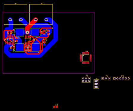
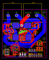
PCB
(
1
/
)
-

PCB_Power_Base
Open in Editor -

PCB
Open in Editor -

PCB_minor_cooling
Open in Editor -

PCB_ready
Open in Editor
The preview image was not generated, please save it again in the
editor.
| ID | Name | Designator | Footprint | Quantity |
|---|---|---|---|---|
| 1 | IR2101STRPBF | U1,U3 | SOIC-8_150MIL | 2 |
| 2 | HB9500-2P black | P1,P2 | HB9500-2P | 2 |
| 3 | 10uF | C1,C4,C3 | 0805 | 3 |
| 4 | 2.2uF | C2,C5 | 0805 | 2 |
| 5 | IRLR7843TRPBF | Q1,Q2,Q3,Q4 | TO-252-2 | 4 |
| 6 | 100 | R1,R2,R3,R4 | 0805 | 4 |
| 7 | 1N4148WS | D1,D2 | SOD-323-F | 2 |
| 8 | 120 | R5 | 0805 | 1 |
| 9 | pot_pad | A1 | POTENTIOMETER PADS | 1 |
| 10 | 56 | R6,R7 | 0805 | 2 |
| 11 | Header-Male-2.54_1x3 | P4 | HDR-3X1/2.54 | 1 |
| 12 | 2SC5050VGB0WR003 | LED | LED-WS2813B-B | 1 |
| 13 | Header-Male-2.54_2x3 | P3 | HDR-3X2/2.54 | 1 |
| 14 | ATMEGA88PA-AU | U4 | TQFP-32_7X7X08P | 1 |
| 15 | Header-Female-2.54_1x6 | P5 | HDR-6X1/2.54 | 1 |
| 16 | Testpoint | INT0,INT1 | TP | 2 |
Unfold
Project Members


 0
0
 0
0
Collect to album
Related Projects
Change a batch
Loading...
Add to album
×
Loading...
reminder
×
Do you need to add this project to the album?