


© 2024 EasyEDA Some rights reserved ISO/IEC
Editor Version
×
Standard

1.Easy to use and quick to get started
2.The process supports design scales of 300 devices or 1000 pads
3.Supports simple circuit simulation
4.For students, teachers, creators
Profession

1.Brand new interactions and interfaces
2.Smooth support for design sizes of over 5,000 devices or 10,000 pads
3.More rigorous design constraints, more standardized processes
4.For enterprises, more professional users

Ongoing
STD JLCPCB Solution: Black Eye Independent Camera Control Module
Mode: Editors' pick
- 0
Update time:
2020-05-09 01:43:52
Creation time:
2020-05-07 08:28:02
Description
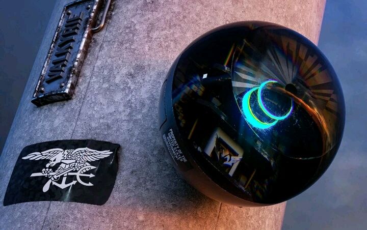
This Project stimulates the Black Eye in Rainbow Six® Siege.
The main function of this product is controlling the Camera movement by NRF.
This article was sponsored by JLCPCB the largest PCB prototype company in China.
Step 1: Project Development Tools
1 MCU Development
MCU: Atmega 32U4
Developed by Arduino. The Atmega 32u4 corresponds to Leonardo of the Arduino
2 Pcb Layout by [EasyEDA](EasyEDA); PCB prototype by [JLCPCB](JLCPCB); Parts Sourcing in [lcsc](LCSC)
3 3D Software by SolidWorks
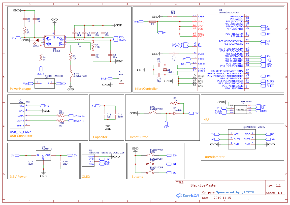
Step 2: The Master
3.1.1 operation mechanism: After the control panel starts, the setup() part is initialized.
1) initialize the NRF module and start the ACK mode.
2) initialize Analog IO: A0 A1. Corresponding rocker potentiometer.
3) initialization button interrupt. Buttons use interrupts directly for input instead of scanning. Anyway, enough interrupts for XD)
4) initialize the OLED and display a two-second Black Eye icon.
After the initialization is complete, the control board in the loop() will continue to send data through the NRF (command 7) and attempt to retrieve the ACK return package.
If the data of the returned package is returned correctly, the connection is successful and the screen enters working mode.
The ACK return packet contains the following information: steering gear speed, battery voltage, chart transfer switch status, steering gear switch status.
No matter whether the connection is successful or not, the control board will still send the control command:
Command 1/2/3/4: used to control steering gear
Command 5/6/8: used to control steering gear power/chart power/change steering gear speed
Sending Command7 without a reply for more than 3 seconds is considered a disconnected connection.
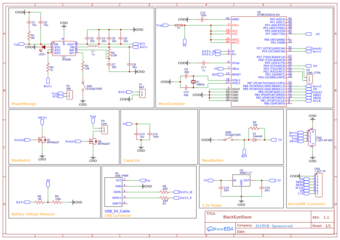
Step 3: The Master
3.2 the Master 3.2.1 operation mechanism: Similar to Master, setup() does NRF and IO initialization. A0 gets the battery voltage, and the control1/2 is used to switch on and off the MOS tube that controls the graph transmission and the steering gear power supply.
In the loop(), commands from the Master will be received repeatedly, processed, and returned via an ack.
Step 4: The Schematic Diagram
The schematic diagram in easyeda.com
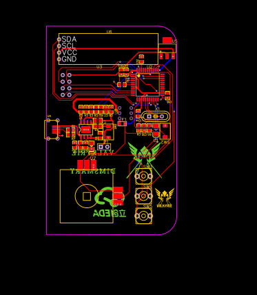
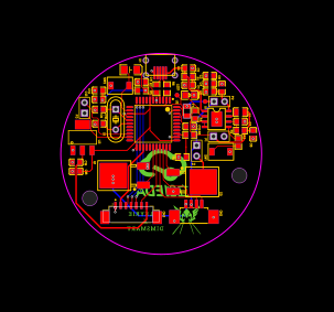
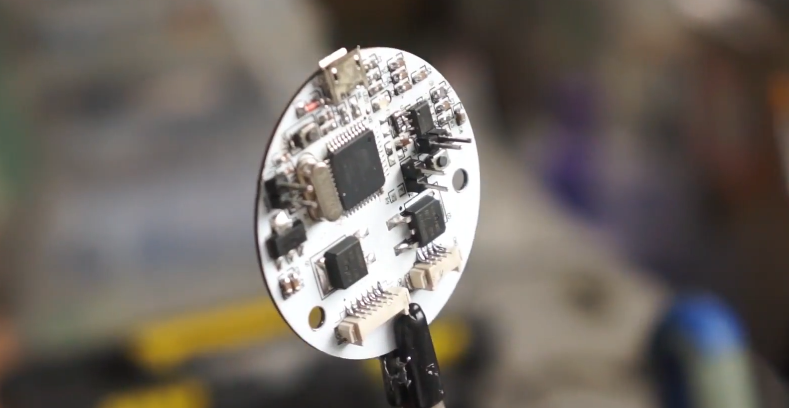
Step 5: PCB
The PCB manufactured in [JLCPCB](JLCPCB) which only charges $2 for 5 pcs PCB Prototype within 2 days.
Design Drawing
schematic diagram
(
1
/
)
PCB
(
1
/
)
The preview image was not generated, please save it again in the
editor.
BOM
Project Members


 0
0
 0
0
Collect to album
Target complaint
Related Projects
Change a batch
Loading...
Add to album
×
Loading...
reminder
×
Do you need to add this project to the album?