


© 2024 EasyEDA Some rights reserved ISO/IEC
Editor Version
×
Standard

1.Easy to use and quick to get started
2.The process supports design scales of 300 devices or 1000 pads
3.Supports simple circuit simulation
4.For students, teachers, creators
Profession

1.Brand new interactions and interfaces
2.Smooth support for design sizes of over 5,000 devices or 10,000 pads
3.More rigorous design constraints, more standardized processes
4.For enterprises, more professional users
Ongoing
STD SparkFun Electric Imp imp002 Breakout
Mode: Editors' pick
- 1
Update time:
2021-04-12 08:29:37
Creation time:
2016-07-15 02:56:26
Description
![enter image description here][1]
![enter image description here][2]
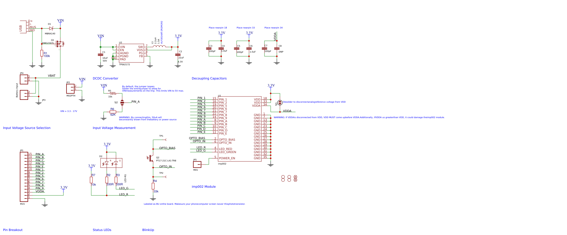
**Description:** If you aren’t familiar with the Electric Imp, it essentially provides an easy, integrated way to connect almost any hardware device both to other devices and to Internet services. The SparkFun Electric Imp imp002 Breakout allows you to explore the capabilities of the Imp product line in an easy to use package! The imp002 is actually a solder-down module version of the original Imp card and we have done the hard work of creating a breakout board for you. Now, you just need one board instead two (the Imp card and the original Imp breakout) to get started with the Electric Imp!
The imp002 breakout board contains a 3.3V TPS62172 step-down regulator (and the inductor/capacitors supporting it). This regulator allows for input voltages anywhere between 3.3V and 17V (voltages in the upper end of that range may produce some heat). This breakout can even support up to 500mA of continuous current. Like the Imp card, the imp002 module contains an embedded ARM Cortex-M3 microprocessor, an onboard WiFi module, and an antenna. Additionally, we have broken out 12 I/O pins from the imp002 module to standard 0.1" headers. Much like the Imp card, these pins can be used for a variety of functions.
**Note:** Check out the Hookup Guide in the Documents section below to learn how to, not only, how to set up imp002 Breakout but also a few fun circuit experiments as well!
For more detail and Documents, Please visit: http://www.sparkfun.com/products/12958
[1]: /editor/20160717/578b4c2b3a76e.png
[2]: /editor/20160717/578b4c2ee7b6d.png
Design Drawing
schematic diagram
(
1
/
)
PCB
(
1
/
)
The preview image was not generated, please save it again in the
editor.
| ID | Name | Designator | Footprint | Quantity |
|---|---|---|---|---|
| 1 | imp002 | U1 | ELECTRIC_IMP_IMP002 | 1 |
| 2 | 22uF | C2 | 0805 | 1 |
| 3 | 2.2uH | L1 | VLF4012A | 1 |
| 4 | TPS62172 | U2 | WSON-8-PAD | 1 |
| 5 | 10uF | C1 | 1210 | 1 |
| 6 | M02PTH | JP2,JP4 | 1X02 | 2 |
| 7 | USB | X1 | USB-MINIB | 1 |
| 8 | DMG2307L | Q1 | SOT-23 | 1 |
| 9 | M02-JST-2MM-SMT | JP3 | JST-2-SMD | 1 |
| 10 | 100pF | C3,C5,C7 | C-0603 | 3 |
| 11 | 1.0uF | C4,C6 | C-0603 | 2 |
| 12 | DNP | C8 | C-0603 | 1 |
| 13 | JUMPER-PAD-2-NC_BY_PASTE | SJ1 | PAD-JUMPER-2-NC_BY_PASTE_YES_SILK | 1 |
| 14 | PT17-21C-L41-TR8 | Q2 | PT17-21C-L41-TR8 | 1 |
| 15 | LED-RG | D2 | LTST-C195KGJRKT | 1 |
| 16 | M15 | JP1 | 1X15 | 1 |
| 17 | M01 | JP5 | 1X01 | 1 |
| 18 | FIDUCIAL | FID1,FID2 | FIDUCIAL-1X2 | 2 |
| 19 | STAND-OFF | STANDOFF1,STANDOFF2,STANDOFF3,STANDOFF4 | STAND-OFF | 4 |
| 20 | MBRA140 | D1 | SMA-DIODE | 1 |
| 21 | JUMPER-PAD-3-NO | SJ2 | PAD-JUMPER-3-NO_YES_SILK_FULL_BOX | 1 |
| 22 | 33k | R5 | 0603-RES | 1 |
| 23 | TEST-POINT | TP1,TP2 | PAD.03X.05 | 2 |
| 24 | 100k | R1 | 3-0603 | 1 |
| 25 | 62K | R6 | 3-0603 | 1 |
| 26 | 33k | R4 | 3-0603 | 1 |
| 27 | 10k | R7 | 3-0603 | 1 |
| 28 | 330R | R2,R3 | 3-0603 | 2 |
Unfold
Project Members


 0
0
 1
1
Collect to album
Related Projects
Change a batch
Loading...
Add to album
×
Loading...
reminder
×
Do you need to add this project to the album?