


© 2024 EasyEDA Some rights reserved ISO/IEC
Editor Version
×
Standard

1.Easy to use and quick to get started
2.The process supports design scales of 300 devices or 1000 pads
3.Supports simple circuit simulation
4.For students, teachers, creators
Profession

1.Brand new interactions and interfaces
2.Smooth support for design sizes of over 5,000 devices or 10,000 pads
3.More rigorous design constraints, more standardized processes
4.For enterprises, more professional users
Ongoing
STD ECG Arduino shield
License: Public Domain
Mode: Editors' pick
- 3
Update time:
2021-07-29 18:45:15
Creation time:
2017-09-29 20:04:59
Description
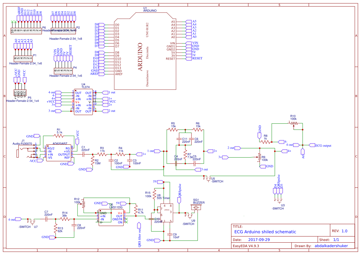
**ECG Arduino shield**
**BACKGROUND KNOWLEDGE**
-Electrocardiogram (ECG/EKG):
it is the electrical activities of the heart. During each heartbeat, a healthy heart has an orderly progression of depolarization that starts with pacemaker cells in the sinoatrial node, spreads out through the atrium, passes through the atrioventricular node down into the bundle of His and into the Purkinje fibers, spreading down and to the left throughout the ventricles. This orderly pattern of depolarization gives rise to the characteristic ECG tracing.
To the trained clinician, an ECG conveys a large amount of information about the structure of the heart and the function of its electrical conduction system. Among other things, an ECG can be used to measure the rate and rhythm of heartbeats, the size and position of the heart chambers, the presence of any damage to the heart's muscle cells or conduction system, the effects of cardiac drugs, and the function of implanted pacemakers.
![figure (1): A normal ECG signal.][1]
A normal ECG signal.
The electrodes are placed on the body of the patient according to universal protocol “12 leads ECG electrodes placement” which include the three basic leads [Bipolar leads]:
Lead (1): The electrodes will be connected to the RA, LA (Right Leg always connected to ground).
Lead (2): The electrodes will be connected to the RA, LL (Right Leg always connected to ground).
Lead (3): The electrodes will be connected to the LL, LA (Right Leg always connected to ground).
![Figure (2): ECG lead connections.][2]
ECG lead connections.
**The aim of the project**
Engineers, particularly biomedical engineers are strongly involved in solving many problems related to human body in which they might need to make use of the natural biological signals of the body [like ECG].
Such biological signal requires reliable safe-to-use bio-amplifiers that can integrate with microcontrollers or other digital systems.
Upon researching this area a gap was found between the Engineering community and the biomedical engineering problems which can be summarized (safety-cost-reliability-time)
The aim of this project is to build low cost safe to use Arduino shields that will help students, lecturers, beginners and developers with no background in electronics and/or programming to get those biological signals in analog form so they can build their projects easily, with high efficiency regarding the size, weight, and outputs.
Extra features were added to each shield to draw more value from such shields like QRS detector, voltage comparator, and monostable timer.
the output will be via the analog pin of the Arduino [Pin0] and the digital Pins [pin3/pin4].
Audio QRS is achieved via a Buzzer
the system has a total Gain of (G=1100), 50Hz Notch filter and bandwidth of the range (0.05Hz to 150Hz)
with optional QRS filter and a bypass switch for the Notch filter
![The obtained ECG signal displayed on an oscilloscope][3]
The obtained ECG signal displayed on an oscilloscope
[1]: /editor/20171201/5a20fece78013.jpg
[2]: /editor/20171201/5a20ff299293d.gif
[3]: /editor/20171201/5a21016c5872a.png
Design Drawing
schematic diagram
(
1
/
)
PCB
(
1
/
)
The preview image was not generated, please save it again in the
editor.
| ID | Name | Designator | Footprint | Quantity |
|---|---|---|---|---|
| 1 | ARDUINO | U1 | ARDUINO | 1 |
| 2 | AD620ARZ | U2,U6 | SOIC-8_150MIL | 2 |
| 3 | Audio-PJ30070 | J1 | AUDIO-PJ307C | 1 |
| 4 | Header-Female-2.54_1x6 | P1,P4 | HDR-6X1/2.54 | 2 |
| 5 | Header-Female-2.54_1x8 | P2,P3 | HDR-8X1/2.54 | 2 |
| 6 | 5.1k | R1 | 0402 | 1 |
| 7 | 220nF | C1 | 0603 | 1 |
| 8 | 15M | R2 | 0402 | 1 |
| 9 | 11k | R3,R4 | 0402 | 2 |
| 10 | 100nF | C2 | 0603 | 1 |
| 11 | 15k | R5,R6 | 0402 | 2 |
| 12 | 100nF | C3 | 0603 | 1 |
| 13 | 220nF | C4,C5,C6,C7,C8,C10,C11 | 0603 | 7 |
| 14 | 7.5k | R7 | 0402 | 1 |
| 15 | 1k | R8,R9 | 0402 | 2 |
| 16 | Header-Female-2.54_1x4 | P5 | 4PinHeader SMD | 1 |
| 17 | 100k | R9,R10,R12,R8,R11 | TRIM_POT_PTH | 5 |
| 18 | TL074 | U4 | SOIC-14_150MIL | 1 |
| 19 | -SWITCH | U5,U7,U9,U3 | CON3 | 4 |
| 20 | LM311DG | U6,U10 | SOIC-8_150mil | 2 |
| 21 | 4.7k | R11,R10 | 0402 | 2 |
| 22 | 62k | R13 | 0402 | 1 |
| 23 | 36k | R14 | 0402 | 1 |
| 24 | 555 Timer | U8 | SOIC8- NA555 Timer | 1 |
| 25 | 10nF | C9 | 0603 | 1 |
| 26 | 100k | R15 | 0402 | 1 |
| 27 | BUZZER | SG1 | BUZZER-12MM | 1 |
| 28 | Header-Female-2.54_1x10 | P6 | HDR-10X1/2.54 | 1 |
| 29 | TL074ACD | U2,U3,U4,U5,U8 | SOIC14N | 5 |
| 30 | 4N25M | U7 | DIP-6 | 1 |
| 31 | 220n | C1,C4,C5 | RAD-0.1 | 3 |
| 32 | 13M | R2 | 0402 | 1 |
| 33 | 100n | C2,C3 | 0603 | 2 |
| 34 | 440n | C6 | RAD-0.1 | 1 |
| 35 | Header-Female-2.54_1x4 | P5 | HDR-4X1/2.54 | 1 |
| 36 | TL074 | U9 | DIP14 | 1 |
Unfold
Project Members


 1
1
 3
3
Collect to album
Target complaint
Related Projects
Change a batch
Loading...
Add to album
×
Loading...
reminder
×
Do you need to add this project to the album?