


© 2024 EasyEDA Some rights reserved ISO/IEC
Editor Version
×
Standard

1.Easy to use and quick to get started
2.The process supports design scales of 300 devices or 1000 pads
3.Supports simple circuit simulation
4.For students, teachers, creators
Profession

1.Brand new interactions and interfaces
2.Smooth support for design sizes of over 5,000 devices or 10,000 pads
3.More rigorous design constraints, more standardized processes
4.For enterprises, more professional users
Ongoing
STD Simulation of the Sharp GP2Y1010AU0F dust sensor module
License: Public Domain
Mode: Editors' pick
- 0
Update time:
2021-04-09 17:13:46
Creation time:
2016-09-06 15:36:13
Description
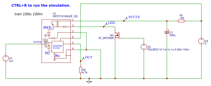
Simulation of the Sharp GP2Y1010AU0F optical IR dust sensor module using the in-house EasyEDA GP2Y1010AU0F_EE model.
GP2Y1010AU0F device page:
https://www.sharpsde.com/products/optoelectronic-components/model/GP2Y1010AU0F/
Datasheet:
https://cdn.sharpsde.com/fileadmin/products/Optoelectronics/Sensors/Specs/GP2Y1010AU0F_20Jul07_Spec_ED-05G124B.pdf
https://www.sparkfun.com/datasheets/Sensors/gp2y1010au_e.pdf
Applications note:
http://www.sharp-world.com/products/device/lineup/data/pdf/datasheet/gp2y1010au_appl_e.pdf
### GP2Y1010AU0F_EE notes.
1) GP2Y1010AU0F_EE is a simple behavioural model only.
2) The model has a 7th pin which is not present in the real device.
This pin, DUSTIN, is a high impedance input used to allow a voltage representing dust density in mg/m^3 to be supplied to the model in order to generate an output voltage in response to a pulse input to the LED driver circuit.
The DUSTIN input is scaled so that 1V represents 1mg/m^3.
3) The output is scaled at 5V/(mg/m^3) with an offset, VOC of 0.9V and a maximum saturated out put VOH of 3.6V.
4) Output resistance is not specified in the device literature but is set in this model to an arbitrary 100R.
5) In the opinion of the model designer, the current drain of the LED driver stage is very poorly specified and the datasheet definition of the `LED terminal current` of `ILED` is misleading.
The `LED` control input pin (pin 3) is supposed to be a 'low power' control input. Given the circuit shown for the LED driver, a control current of 10mA would imply that the LED current being controlled is *much* larger: in the region of 100mA or maybe more. The external circuit of 150R and 220uF together with the quoted 0.32ms pulse width at 10ms period. It is therefore likely that the current drawn by the VLED pin (pin 1) is something like 110mA (100mA for the IRED itself plus 10mA for the current out of the LED pin) for the duration of the LED being on.
Hence for the purposes of this model, an arbitrary LED current of 100mA has been assumed together with the quoted ILED of 10mA. Both of these currents are assumed to be zero when the LED is off.
If anyone would like to submit measured values for the operating current into pin 1 and out of pin 3 of this device that would be very helpful in continuing the development of this model.
Please email measurements and detailed documentation of how the measurements were carried out to support at easyeda.com.
Thanks.
Design Drawing
schematic diagram
(
1
/
)
PCB
(
1
/
)
The preview image was not generated, please save it again in the
editor.
| ID | Name | Designator | Footprint | Quantity |
|---|---|---|---|---|
| 1 | GP2Y1010AU0F_EE | U1 | DIP8_400mil_WIDEBODY | 1 |
| 2 | 150 | R1 | R0805 | 1 |
| 3 | 220u | C1 | CP_8X13MM | 1 |
| 4 | DI_2N7002K | M1 | NONE | 1 |
| 5 | 0.5 | V1 | 2P-5.0 | 1 |
| 6 | 5 | V2 | 2P-5.0 | 1 |
| 7 | PULSE(0 10 1m 1u 1u 0.32m 10m) | V3 | 2P-5.0 | 1 |
| 8 | 4.7k | R2 | R0805 | 1 |
Unfold
Project Members


 0
0
 0
0
Collect to album
Target complaint
Related Projects
Change a batch
Loading...
Add to album
×
Loading...
reminder
×
Do you need to add this project to the album?