


© 2024 EasyEDA Some rights reserved ISO/IEC
Editor Version
×
Standard

1.Easy to use and quick to get started
2.The process supports design scales of 300 devices or 1000 pads
3.Supports simple circuit simulation
4.For students, teachers, creators
Profession

1.Brand new interactions and interfaces
2.Smooth support for design sizes of over 5,000 devices or 10,000 pads
3.More rigorous design constraints, more standardized processes
4.For enterprises, more professional users
Ongoing
STD P-MOSFET PWD Shield
Mode: Editors' pick
- 0
Update time:
2021-04-10 12:32:06
Creation time:
2015-12-11 08:31:51
Description
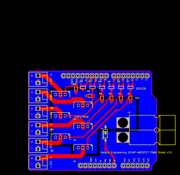
2 layer board of 2.71x2.11 inches (68.73x53.47 mm).
For when you need to switch the positive side of your load (common cathode) instead of the negative side (common anode). Most FET shields use N-Channel MOSFETs which switch the ground connection, assuming the positive connection is always connected to power. This shield uses P-Channel MOSFETs which switch the positive, so it’ll work with loads that have a common ground (like this aquarium light )
The input is designed to take a PCB mounted Anderson PowerPole connector, but you can solder wires directly to it just as easily.
Components are as labeled on the board:
FQP27P06
BSS138
10k 1206 SMT resistor (take your pick)
1N4148 or any other rectifying diode. It’s just there to prevent the Arduino from trying to feed power to a potentially large load hanging off the MOSFETs.
Design Drawing
schematic diagram
(
1
/
)
PCB
(
1
/
)
The preview image was not generated, please save it again in the
editor.
BOM
Project Members


 0
0
 0
0
Collect to album
Target complaint
Related Projects
Change a batch
Loading...
Add to album
×
Loading...
reminder
×
Do you need to add this project to the album?