


© 2024 EasyEDA Some rights reserved ISO/IEC
Editor Version
×
Standard

1.Easy to use and quick to get started
2.The process supports design scales of 300 devices or 1000 pads
3.Supports simple circuit simulation
4.For students, teachers, creators
Profession

1.Brand new interactions and interfaces
2.Smooth support for design sizes of over 5,000 devices or 10,000 pads
3.More rigorous design constraints, more standardized processes
4.For enterprises, more professional users

Ongoing
STD ART ESP32 WiFi TFT Thermostat
License: MIT
Mode: Editors' pick
- 6
Update time:
2021-12-05 01:51:15
Creation time:
2020-11-25 21:24:47
Description
My compliments to EasyEDA & OSHWLab & JLCPCB & LCSC for the excellent software and Service  ThumbsUp!
Sorry for my Englisch, Dutch is my Mothers language.
Fabio Mastrotto, by seeing his video He got me into this trouble [https://youtu.be/CM0h_ad7ETU](https://youtu.be/CM0h_ad7ETU)
# ART ESP32 WiFi TFT Touch Clock Thermostat.
## The ART of Temperature controlled.
# http://www.Arduino.TK
The Best NEST Thing ;-)
Part of SMART is ART, ART is SMART.
### Let's make the NEST best Thermostat, Make ART smart.
### Impressive with Espressif
3d view of the PCB [https://youtu.be/dH2b9dbxTJg](https://youtu.be/dH2b9dbxTJg)  3d view of the PCB [https://youtu.be/dH2b9dbxTJg](https://youtu.be/dH2b9dbxTJg) Design a PCB board to connect ESP32 dev kit 38pin to 14 pin SPI Touch TFT screen With some extra Female holes to connect other wires / PCB modules
Got my 4inch SPI Touch TFT LCD from [https://nl.aliexpress.com/item/4001122632293.html](https://nl.aliexpress.com/item/4001122632293.html)
3.2inch 14pin SPI TFT Touch ili9341 = supported by TFT_eSPI library [https://www.google.com/search?q=aliexpress+SKU%3AMSP3218](https://www.google.com/search?q=aliexpress+SKU%3AMSP3218) [http://www\.lcdwiki\.com/3\.2inch\_SPI\_Module\_ILI9341\_SKU:MSP3218](http://www.lcdwiki.com/3.2inch_SPI_Module_ILI9341_SKU:MSP3218) [http://www.lcdwiki.com/images/d/d4/MSP3218-size.jpg](http://www.lcdwiki.com/images/d/d4/MSP3218-size.jpg)
3.5inch 14pin SPI TFT Touch ili9488 = supported by TFT_eSPI library [https://www.google.com/search?q=aliexpress+SKU%3AMSP3520](https://www.google.com/search?q=aliexpress+SKU%3AMSP3520) [http://www\.lcdwiki\.com/3\.5inch\_SPI\_Module\_ILI9488\_SKU:MSP3520](http://www.lcdwiki.com/3.5inch_SPI_Module_ILI9488_SKU:MSP3520) [http://www\.lcdwiki\.com/images/2/20/3\.5inch\_SPI\_Size\.png](http://www.lcdwiki.com/images/2/20/3.5inch_SPI_Size.png)
4inch 14pin SPI TFT Touch ili7796 = supported by TFT_eSPI library [https://www.google.com/search?q=aliexpress+SKU%3AMSP4021](https://www.google.com/search?q=aliexpress+SKU%3AMSP4021) [http://www\.lcdwiki\.com/4\.0inch\_SPI\_Module\_ST7796](http://www.lcdwiki.com/4.0inch_SPI_Module_ST7796) [http://www\.lcdwiki\.com/zh/images/b/b4/4\.0inch\_SPI\_size\.png](http://www.lcdwiki.com/zh/images/b/b4/4.0inch_SPI_size.png)
Maybe also add a connector for
NTC Thermistor KY-013 Like the resolution of a NTC Thermistor prefer a NTC above big steps off digital sensor (But MayBe BME280 is an good one) ESP32 analog read example ESP32 Note: Analog noise and fluctuences with analog read => multiread and capacitor [https://docs.espressif.com/projects/esp-idf/en/latest/esp32/api-reference/peripherals/adc.html](https://docs.espressif.com/projects/esp-idf/en/latest/esp32/api-reference/peripherals/adc.html) Not so clear for me as DIY Tinker => think they want a 0.1mf 100uf capacitor between signal and ground to damp the analog read ``` // ESP32 analog read test // KY-013 NTC thermistor signal is connected to GPIO 34 (Analog ADC1_CH6) // KY-013 NTC thermistor - is connected to 3.3V //strange but correct - to +3.3V // KY-013 NTC thermistor + is connected to GND //strange but correct + to GND // outputs Fahrenheit and Celcius to serial monitor // https://oshwlab.com/l.dijkman/esp32-dev-kit-38-pin-to-spi-touch-tft // https://github.com/ldijkman/ART-ESP32-Touch-TFT-Thermostat // http://www.Arduino.TK // // https://www.google.com/search?q=3+fahrenheit+to+celsius int ThermistorPin = 34; //gpio34 int Vo; float R1 = 10000; float logR2, R2, T, Tc, Tf; float c1 = 1.009249522e-03, c2 = 2.378405444e-04, c3 = 2.019202697e-07; float voltage = 3.3; //use 3.3volt void setup() { Serial.begin(115200); //serial monitor } void loop() { Vo = 0; for (int i = 0; i https://lastminuteengineers.com/esp32-ntp-server-date-time-tutorial/](https://lastminuteengineers.com/esp32-ntp-server-date-time-tutorial/) [Mine NTP =\> https://youtu.be/m04PbIkMzjE](https://youtu.be/m04PbIkMzjE)
OhOh => i used SDA wich is Hardware gpio i2c want to use it for RTC DS3231 solution wire.h => softwarei2c on other gpio pins [https://randomnerdtutorials.com/esp32-i2c-communication-arduino-ide/#3](https://randomnerdtutorials.com/esp32-i2c-communication-arduino-ide/#3)  ``` // ESP32 I2C RTC DS3231 realtimeclock test // sets the time on DS3231 from computer when progam loads // and print inforation about time and date to serial monitor // software i2c on other i/o = non hardware i2c // ART ESP32Thermostat by luberth dijkman // https://oshwlab.com/l.dijkman/esp32-dev-kit-38-pin-to-spi-touch-tft // https://github.com/ldijkman/ART-ESP32-Touch-TFT-Thermostat // http://www.Arduino.TK #include #define I2C_SDA 33 //gpio33 #define I2C_SCL 32 //gpio32 #include "RTClib.h" // https://github.com/adafruit/RTClib RTC_DS3231 rtc; // download zip from above and install library from zip char daysOfTheWeek[7][12] = {"Sunday", "Monday", "Tuesday", "Wednesday", "Thursday", "Friday", "Saturday"}; void setup(void) { Wire.begin(I2C_SDA, I2C_SCL); Serial.begin(115200); if (! rtc.begin()) { Serial.println("Couldn't find RTC"); Serial.flush(); abort(); } if (rtc.lostPower()) { Serial.println("RTC lost power, let's set the time!"); // When time needs to be set on a new device, or after a power loss, the // following line sets the RTC to the date & time this sketch was compiled rtc.adjust(DateTime(F(__DATE__), F(__TIME__))); // This line sets the RTC with an explicit date & time, for example to set // January 21, 2014 at 3am you would call: // rtc.adjust(DateTime(2014, 1, 21, 3, 0, 0)); } // When time needs to be re-set on a previously configured device, the // following line sets the RTC to the date & time this sketch was compiled // rtc.adjust(DateTime(F(__DATE__), F(__TIME__))); // This line sets the RTC with an explicit date & time, for example to set // January 21, 2014 at 3am you would call: // rtc.adjust(DateTime(2014, 1, 21, 3, 0, 0)); } void loop () { DateTime now = rtc.now(); Serial.print(now.year(), DEC); Serial.print('/'); Serial.print(now.month(), DEC); Serial.print('/'); Serial.print(now.day(), DEC); Serial.print(" ("); Serial.print(daysOfTheWeek[now.dayOfTheWeek()]); Serial.print(") "); Serial.print(now.hour(), DEC); Serial.print(':'); Serial.print(now.minute(), DEC); Serial.print(':'); Serial.print(now.second(), DEC); Serial.println(); Serial.print("Temperature: "); Serial.print(rtc.getTemperature()); Serial.println(" C"); Serial.println(); delay(1000); } ```
image from Paul Stofregen example image what i want, a board to connect ESP32 to SPI TFT 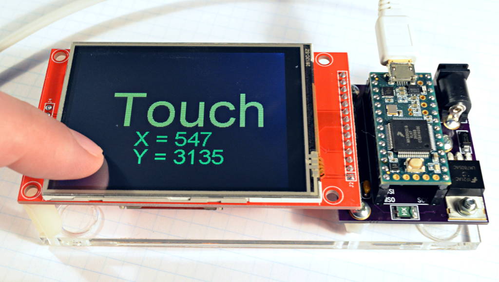
example image what i want, a board to connect ESP32 to SPI TFT image from Paul Stofregen
[https://nl.aliexpress.com/item/4000415147087.html](https://nl.aliexpress.com/item/4000415147087.html) 38pin ESP32 dev kit Can anyone tell me the SKU number for this module => post a comment on the bottom of page?
 **NOTE:** LEFT BOTTOM above V5 is CMD FLASH / GPIO11 not **GND, yep i did it ;-(**  **NOTE:** LEFT BOTTOM above V5 is CMD FLASH / GPIO11 not **GND, yep i did it ;-(**
Can anyone tell me the SKU number for this module => post a comment on the bottom of page? 38pin ESP32 dev kit [https://nl.aliexpress.com/item/4000415147087.html](https://nl.aliexpress.com/item/4000415147087.html)  **NOTE**: LEFT BOTTOM above V5 is CMD FLASH / GPIO11 not **GND, yep i did it ;-(** Can anyone tell me the SKU number for this module => post a comment on the bottom of page? Think this one has a better pin description not the same PCB placement of components but pinout is the same
 Think this one has a better pin description not the same PCB placement of components but pinout is the same #### a schematic of a ESP32 38pin [https://dl\.espressif\.com/dl/schematics/esp32\_devkitc\_v4\-sch\.pdf](https://dl.espressif.com/dl/schematics/esp32_devkitc_v4-sch.pdf)
# Free Arduino IDE = SourceCode Editor / Compiler / Programmer [https://www.arduino.cc/en/software](https://www.arduino.cc/en/software) My Arduino IDE Settings for this ESP32 38pin dev kit  Arduino IDE [https://www.arduino.cc/en/software](https://www.arduino.cc/en/software) my arduino ide Settings for this ESP32 38pin dev kit
## Next adds ESP8266 and ESP32 boards to the Arduino IDE File => preferences => aditional board managers [http://arduino\.esp8266\.com/stable/package\_esp8266com\_index\.json](http://arduino.esp8266.com/stable/package_esp8266com_index.json) [https://dl\.espressif\.com/dl/package\_esp32\_index\.json](https://dl.espressif.com/dl/package_esp32_index.json)

File => preferences => aditional board managers [http://arduino\.esp8266\.com/stable/package\_esp8266com\_index\.json](http://arduino.esp8266.com/stable/package_esp8266com_index.json) [https://dl\.espressif\.com/dl/package\_esp32\_index\.json](https://dl.espressif.com/dl/package_esp32_index.json)
TFT_eSPI library would like to use the pinout from [https://github.com/Bodmer/TFT_eSPI](https://github.com/Bodmer/TFT_eSPI) like this TFT SPI library much like the touch calibration process of this library much / perfect TFT_eSPI ESP32 wroom 32 dev kit 38pin - SPI TFT ST7796 touch [https://github.com/Bodmer/TFT_eSPI](https://github.com/Bodmer/TFT_eSPI) touch calibration
# To install TFT_eSPI in Arduino IDE Download the ZIP from [https://github.com/Bodmer/TFT_eSPI](https://github.com/Bodmer/TFT_eSPI) and install library from ZIP Then you have an up to date version File => Examples => TFT_eSPI there are a lot off examples to play with

Edit /home/pi/Arduino/libraries/TFT\_eSPI/User\_Setup\.h \(Path willl be a bit different on a MicroSoft Windows PC\) With a text editor to meet your display and microprocessor
or include the file in arduino IDE as a TAB Sketch => Add File and edit the User_Setup.h in Arduino IDE to meet your hardware Specs  
* This is wat your Arduino IDE should look like, Main File with the TAB files ART\_ESP32\_Thermostat\_7\_12\_2020\_ver2\.ino =\> is the Main File The other files are included tab files (Should be in the same Directory as Main File) 
HOWTO ESP32 to SPI TFT by Xtronical [https://www.youtube.com/watch?v=rq5yPJbX_uk](https://www.youtube.com/watch?v=rq5yPJbX_uk)
SPI TFT ST7796 touch Hope i did not make any mistakes but i Solemnly Swear, sincerely honestly believe ;-) this is my pinout Some notes on WiFi and analog ports [https://microcontrollerslab.com/adc-esp32-measuring-voltage-example/](https://microcontrollerslab.com/adc-esp32-measuring-voltage-example/)
TABLE data from LCDWIKI [http://www\.lcdwiki\.com/3\.2inch\_SPI\_Module\_ILI9341\_SKU:MSP3218](http://www.lcdwiki.com/3.2inch_SPI_Module_ILI9341_SKU:MSP3218) [http://www\.lcdwiki\.com/3\.5inch\_SPI\_Module\_ILI9488\_SKU:MSP3520](http://www.lcdwiki.com/3.5inch_SPI_Module_ILI9488_SKU:MSP3520) [http://www\.lcdwiki\.com/4\.0inch\_SPI\_Module\_ST7796](http://www.lcdwiki.com/4.0inch_SPI_Module_ST7796)
| Number | Pin label | Description | =======> | Connected to | | ------ | --------- | ----------- | -------- | ------------ | | 1 | VCC | 5V or 3.3V power input | | 5V
according lcdwiki schematic
TFT has own U1=3,3 voltage regulator
wich powers TFT ic's
so safe for ESP32
5VCC only for brighter backLED
backled is switched by a transistor LED
maybe even better to use 5V for backlight
no extra load for ESP32 onboard 3.3V regulator
i think the 5V is comming from USB
[https://dl\.espressif\.com/dl/schematics/esp32\_devkitc\_v4\-sch\.pdf](https://dl.espressif.com/dl/schematics/esp32_devkitc_v4-sch.pdf) | | 2 | GND | Ground | | GND | | 3 | CS | LCD chip select signal, low level enable | | Gpio 15 | | 4 | RESET | LCD reset signal, low level reset | | Gpio 4 | | 5 | DC/RS | LCD command / data selection signal,
high level: command, low level: data | | Gpio 2 | | 6 | SDI(MOSI) | LCD SPI bus write data signal | | Gpio 23 | | 7 | SCK | LCD SPI bus clock signal | | Gpio 18 | | 8 | LED | Backlight control, high level lighting,
if not controlled, connect 3.3V always bright | | 3.3V or Gpio 32 | | 9 | SDO(MISO) | SPI bus read data signal,
if you do not need to the read function,
you can not connect it | | Not used
Some Say
Possible problems when SDO(MISO) connected
[https://github.com/Bodmer/TFT_eSPI/issues/849](https://github.com/Bodmer/TFT_eSPI/issues/849) | | | | | | | The following is the touch screen signal line wiring, | Number | Pin label | Description | ======> | Connected to | | ------ | --------- | ----------- | ------- | ------------ | | 10 | T_CLK | Touch SPI bus clock signal | | Gpio 18 | | 11 | T_CS | Touch screen chip select signal, low level enable | | Gpio 21 | | 12 | T_DIN | Touch SPI bus input | | Gpio 23 | | 13 | T_DO | Touch SPI bus output | | Gpio19 | | 14 | T_IRQ | Touch screen interrupt signal,
low level when touch is detected | | Not used | | | | | | |
some notes on WiFi and analog ports [https://microcontrollerslab.com/adc-esp32-measuring-voltage-example/](https://microcontrollerslab.com/adc-esp32-measuring-voltage-example/)
| Other pins based on the example code on this page | | | | | ------------------------------------------------- | --- | --- | --- | | NTC Thermistor | | | Gpio 34 | | Relays | | | Gpio 26 | | Buzzer | | | Gpio 12 | | Other pins based on the example code on this page | | | | | ------------------------------------------------- | --- | --- | --- | | I2C SDA
DS3231RealTimeClock | | | Gpio 33 | | I2C SCL
DS3231RealTimeClock | | | Gpio 32 | | Backlight brightness control
LED connection on SPI Connector TF | | | Gpio32
used by i2c
must test another | | | | | | | | | | | | | | | | | | | | |
SD card not used by me HOWTO ESP32 to SPI TFT by Xtronical [https://www.youtube.com/watch?v=rq5yPJbX_uk](https://www.youtube.com/watch?v=rq5yPJbX_uk)
| Silk name | Description | | | Connects to SPI or ESP32 | | --------- | ----------- | --- | --- | ------------------------ | | SD_CS | Chip Select? | | | [https://www.youtube.com/watch?v=rq5yPJbX_uk](https://www.youtube.com/watch?v=rq5yPJbX_uk)
Tell me if you have figured it out from above video
I think Gpio 5 | | SD_MOSI | DATA IN? | | | To SPI header => SDI(MOSI) => Gpio 23 | | SD_MISO | DATA OUT? | | | To SPI header => T_DO => Gpio 19 | | SD_SCK | Clock? | | | To SPI header => SCK => Gpio 18 | | | | | | i think the pinning in the SDcard jpeg demo
TFT\_eSPI/examples/generic/ESP32\_SDcard\_jpeg/
pinning from video is different as above
[https://www.youtube.com/watch?v=rq5yPJbX_uk](https://www.youtube.com/watch?v=rq5yPJbX_uk) | | | | | | |
[Make an LED fade using a PWM signal on the ESP32 =\> http://techexplorations.com/guides/esp32/begin/pwm/](https://techexplorations.com/guides/esp32/begin/pwm/) CUT the 3.3v trace and put a jumper wire GPIO32 to LED Possibility to dim the screen during evening/night hours on time => to save energy => Suggestion from Jo from Belgium Bright Light up on touch? for ?? time ``` // ESP32 test SPI TFT backlight PWM brightnes // PWM = Pulse Width Modulation or pulse-duration modulation // more or less PWM creates a voltage from 0 to 3.3volt on gpio 32 // But SPI connector LED goes to a transistor on the TFT PCB wich switches the VCC wich i have connected to 5Volt // https://oshwlab.com/l.dijkman/esp32-dev-kit-38-pin-to-spi-touch-tft // https://github.com/ldijkman/ART-ESP32-Touch-TFT-Thermostat // http://www.Arduino.TK const int ledPin = 32; // corresponds to GPIO32 // connect to LED of SPI TFT display // setting PWM properties const int freq = 4000; // 4khz const int ledChannel = 1; // think channel 0 is in use by buzzer const int resolution = 8; // 8bit 0 to 255 void setup(){ // configure LED PWM functionalitites ledcSetup(ledChannel, freq, resolution); // attach the channel to the GPIO to be controlled ledcAttachPin(ledPin, ledChannel); } void loop(){ // increase the LED brightness for(int dutyCycle = 0; dutyCycle = 0; dutyCycle--){ // changing the LED brightness with PWM ledcWrite(ledChannel, dutyCycle); delay(15); } } ```
[https://www.youtube.com/user/LuberthDijkman/videos](https://www.youtube.com/user/LuberthDijkman/videos) Arduino Mega Thermostat The Best Nest Thing. ;-) The Nest Best Thing. [https://youtu.be/lny7J7KXk9w](https://youtu.be/lny7J7KXk9w)  [Arduino Mega Thermostat](https://www.youtube.com/watch?v=lny7J7KXk9w) [The Best Nest Thing. ;-\) The Nest Best Thing.](https://www.youtube.com/watch?v=lny7J7KXk9w) [https://youtu.be/lny7J7KXk9w](https://www.youtube.com/watch?v=lny7J7KXk9w)
[https://github.com/Bodmer/TFT_eSPI/issues/849](https://github.com/Bodmer/TFT_eSPI/issues/849)
Thermostat remote control html web interface test layout test various various html input elements on different devices be surprised by the difference [https://jsfiddle.net/luberth/b6y53cn0](https://jsfiddle.net/luberth/b6y53cn0) [https://jsfiddle.net/luberth/b6y53cn0/embedded/result/](https://jsfiddle.net/luberth/b6y53cn0/embedded/result/) Try it on your phone or tablet or pc in differen browsers and be surprised

Thermostat remote control html web interface test layout test various various html input elements on different devices be surprised by the difference [https://jsfiddle.net/luberth/b6y53cn0](https://jsfiddle.net/luberth/b6y53cn0) [https://jsfiddle.net/luberth/b6y53cn0/embedded/result/](https://jsfiddle.net/luberth/b6y53cn0/embedded/result/)
# Do not hardcode WiFi settings Connect with a Phone to the ESP 32 WiFi => ART Thermostat AccesPoint (AP) and Browse to 192.168.4.1 Then you get a html webpage to edit your WiFi RouterName and PassWord settings Save and the ESP32 connects to your WiFi router local network Now lookup the designated ip adress on the touch screen of ART Thermostat Go with the browser to the ipadres in your local network And now you can control ART Thermostat from a webpage If you forward the ip adress in your wifirouter then you can control your ART Thermostat from anywhere in the World ART is Smart!
WEBCONFIG by Jhon Lassen for ESP8266 liked this one for ESP8266 Has dual mode AP=access point =direct connection to a phone and STA is network mode wifi router connected it shows STA network ip adres when in AP=AccessPoint direct connection and possible to do station/network connnect and accespoint connect
WIFIMANAGER by TZAPU for ESP32 [https://youtu.be/m04PbIkMzjE](https://youtu.be/m04PbIkMzjE) does not have dual mode AP+STA does not show ip adress from STA when in AP mode so whe have to show STA ip adress on touch screen most people will find it not handy say hard to lookup gadered STA ip adres in wifi router manager
- - -
# Thermostat Code more will be comming in the future [https://youtu.be/lny7J7KXk9w](https://www.youtube.com/watch?v=lny7J7KXk9w) i have to change the code from arduino mega 2560 to ESP32 and also change it for TFT_eSPI graphic library BUSY WITH THE CONVERSION ART\_ESP32\_Thermostat\_7\_12\_2020\.zip = [https://create.arduino.cc/editor/luberth/5e47cbb4-811d-432f-84ac-8976c56a76c4/preview](https://create.arduino.cc/editor/luberth/5e47cbb4-811d-432f-84ac-8976c56a76c4/preview)
# A Part of Art => SoftWare & HardWare is described @ # [https://github.com/ldijkman/ART-ESP32-Touch-TFT-Thermostat](https://github.com/ldijkman/ART-ESP32-Touch-TFT-Thermostat) i do not understand how github works but trying github is great for the software => you can see when a file is changed github easy 4me to upload new code [https://github.com/ldijkman/ART-ESP32-Touch-TFT-Thermostat](https://github.com/ldijkman/ART-ESP32-Touch-TFT-Thermostat)
## First time EasyEDA.com and JLCPCB.com and LCSC.com == Perfect PCB's! 
Latest Video [https://www.youtube.com/watch?v=qNYT64CaLEI](https://www.youtube.com/watch?v=qNYT64CaLEI) green pixels is just for touch testing => to see if touch is at correct location design is for a smaller screen // ESP32 I2C RTC DS3231 realtimeclock test
# WishList If for 30 seconds screen not touched => hide the buttons animate slide / grow screen to full screen = more space for time, date, barometer, humidity if screen is touched show the buttons again, bit like a menubar on pc_screen hide/show X V let color SetPoint temperature. indicate wich mode is active, eco=green auto=DutchOrange normal/continu=gray V X V Add Cool Mode= iceBlue V Smooth sharp text font store / restore temperture time / week program settings in spifs file system on ESP32 X V time temp week program change times and temp on tft V Design a case, 3D Printer
Design a PCB with all components on it DHL Germany is CRAZY DHL CRAZY TRACKING JLPCB Shenzhen china to hongkong to leipzig to keulen to dusseldorf to leipzig to keulen to dusseldorf to ???  DHL CRAZY TRACKING JLPCB Shenzhen china to hongkong to leipzig to keulen to dusseldorf to leipzig to keulen to dusseldorf to ??? ## ** my first attempt => Wow! Try next inbrowser PCB Designer [https://easyeda\.com/editor\#id=\|476629139fe1472188edc581f8542dac\|652cf902783e44f0b4ff0ab338b8ae5d](https://easyeda.com/editor#id=%7C476629139fe1472188edc581f8542dac%7C652cf902783e44f0b4ff0ab338b8ae5d)
## Learn tutorial easyeda videos [https://youtu.be/MsuR6W-jN5M?list=PLbKMtvtYbdPMZfzGuVTdc0MWKrFvU4nsu](https://youtu.be/MsuR6W-jN5M?list=PLbKMtvtYbdPMZfzGuVTdc0MWKrFvU4nsu)t** ## ***Time for a break, Time for a drink...*** ## \*\*\* [https://www.paypal.com/pools/c/8amUN5rgb9](https://www.paypal.com/pools/c/8amUN5rgb9)\*\*\* Where is the ladder [https://youtu.be/XzO9jGPtrhc](https://youtu.be/XzO9jGPtrhc)
\!\[\]\(file:///home/pi/ART\_ESP32\_Thermostat\.png\) # Like this project ! Share, Follow, ThumbsUp and / or Star this project? Support my work, Support this Project => [http://ww.paypal.me/LDijkman](http://www.paypal.me/LDijkman) # [http://www.Arduino.TK](http://www.Arduino.TK)
Design Drawing
schematic diagram
(
1
/
)
PCB
(
1
/
)
-

try 3
Open in Editor -

PCB_2020-11-29_18-17-28
Open in Editor -

another qr
Open in Editor -

PLsi V0 copy
Open in Editor -

ESP32 Smart Thermostat BME280 DS3231
Open in Editor
The preview image was not generated, please save it again in the
editor.
BOM
Project Members


 2
2
 6
6
Collect to album
Target complaint
Related Projects
Change a batch
Loading...
Add to album
×
Loading...
reminder
×
Do you need to add this project to the album?