


© 2024 EasyEDA Some rights reserved ISO/IEC
Editor Version
×
Standard

1.Easy to use and quick to get started
2.The process supports design scales of 300 devices or 1000 pads
3.Supports simple circuit simulation
4.For students, teachers, creators
Profession

1.Brand new interactions and interfaces
2.Smooth support for design sizes of over 5,000 devices or 10,000 pads
3.More rigorous design constraints, more standardized processes
4.For enterprises, more professional users

Ongoing
STD Mini DSO Oscilloscope
License: Public Domain
Mode: Editors' pick
- 57
Update time:
2024-04-10 17:57:47
Creation time:
2020-07-09 08:41:21
Description
**Specification**
MCU: STC8A8K64S4A12 @27MHz
Display: 0.96" OLED with 128x64 resolution
Controller: One EC11 Encoder
Input: Single Channel
Sec/div: 500ms, 200ms, 100ms, 50ms, 20ms, 10ms, 5ms, 2ms, 1ms, 500us, 200us, 100us
100us only available in Auto Trigger Mode
Voltage Range: 0-30V
Sampling Rating: 250kHz @100us/div
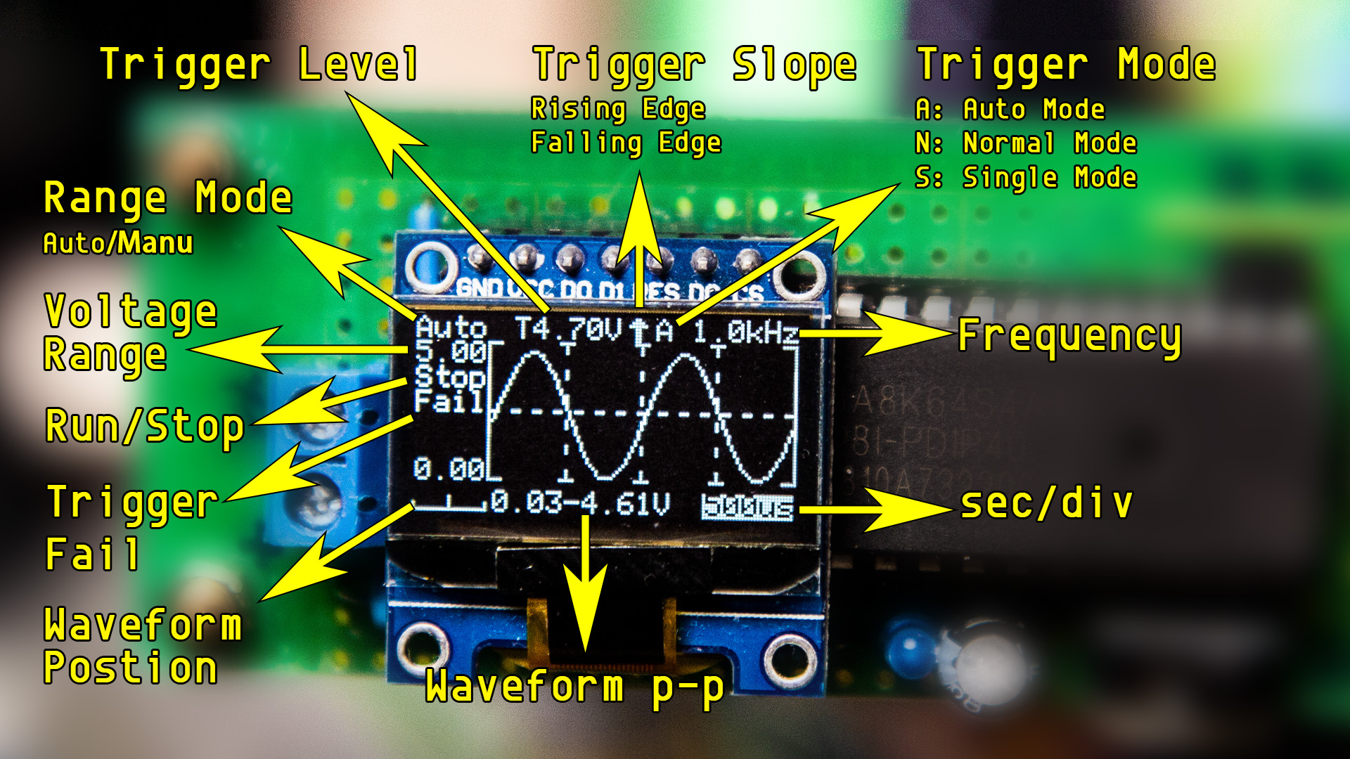
**Parameters in Main Interface:**
Seconds Per Division: "500ms", "200ms", "100ms", "50ms", "20ms", "10ms","5ms", "2ms", "1ms", "500us", "200us", "100us"
100us only available in Auto Trigger Mode.
Voltage Range: 0-30V.
Trigger Level: Trigger voltage level.
Trigger Slope: Trigger on Rising or Falling Edge.
Trigger Mode: Auto Mode, Normal Mode, Single Mode.

**Status in Main Interface:**
'Run': Sampling Running.
'Stop': Sampling Stopped.
'Fail': The Trigger Level beyond the waveform in Auto Trigger Mode.
'Auto': Auto Voltage Range.
**Parameters in Settings Interface:**
PMode(Plot Mode): Show waveform in Vector or Dots.
LSB: Sampling Coefficient. Calibrate the sampling voltage by adjusting LSB.
100 times of voltage dividing coefficient. e.g. the resistor for voltage dividing is 10k and 2k, calculate the voltage dividing coefficient (10+2)/2=6. Get the LSB = 6 x 100 = 600.
BRT(Brightness): Adjust OLED Brightness.
All operations are completed by the EC11 Encoder.
**Main Interface - Parameter Mode**
Single Click Encoder: Run/Stop sampling.
Double Click Encoder: Enter Wave Scroll Mode.
Long Press Encoder: Enter Settings Interface.
Rotate Encoder: Adjust parameters.
Rotate Encoder While Pressing: Switch between options.
Switch Auto and Manual Range: Rotate Encoder clockwise continuous to enter auto range. Rotate Encoder anticlockwise to enter manual range.
**Main Interface - Wave Scroll Mode**
Single Click Encoder: Run/Stop sampling.
Double Click Encoder: Enter Parameter Mode.
Long Press Encoder: Enter Settings Interface.
Rotate Encoder: Scroll waveform horizontally. (only available when sampling stopped)
Rotate Encoder While Pressing: Scroll waveform vertically (only available when sampling stopped)
**Settings Interface**
Single Click Encoder: N/A
Double Click Encoder: N/A
Long Press Encoder: Return to Main Interface.
Rotate Encoder: Adjust parameters.
Rotate Encoder While Pressing: Switch between options.
**Functions**
Trigger Level: For repeating signal, trigger level could make it stable on display.
For single-shot signal, trigger level could capture it.
Trigger Slope: Trigger slope determines whether the trigger point is on the rising or the falling edge of a signal.
Trigger Mode:
Auto Mode: Sweep continuous.
Single click the encoder to stop or run sampling.
If triggered, the waveform will be shown on the display and the trigger position will be put at the center of chart.
Otherwise, the waveform will scroll irregular, and 'Fail' will be shown on the display.
Normal Mode: When complete pre-sampling, you can input signal.
If triggered, waveform shown on the display and waiting for new trigger.
If no new trigger, the waveform will be kept.
Single Mode: When complete pre-sampling, you can input signal.
If triggered, waveform shown on display and stop sampling.
User need to single click Encoder to start next sampling.
For Normal Mode and Single Mode, be sure the trigger level has been adjusted correctly, otherwise no waveform will be shown on the display.
Indicator: Generally, the indicator on means the sampling is running.
The more important use is in Single and Normal Trigger Mode, before get into the trigger stage, pre-sampling is required.
The indicator will not on during pre-sampling stage.
We should not input signal until the indicator comes on.
The longer time scale selected, the longer waiting time of pre-sampling.
Save Settings: When exit settings interface, all parameters in settings and main interface will be saved in EEPROM.


Design Drawing
schematic diagram
(
1
/
)
PCB
(
1
/
)
The preview image was not generated, please save it again in the
editor.
| ID | Name | Designator | Footprint | Quantity |
|---|---|---|---|---|
| 1 | INPUT | CN4 | CONN-TH_DB128V-5.0-2P | 1 |
| 2 | 4.7K | R1 | R0603 | 1 |
| 3 | STC8A8K64S4A12-C83896 | U1 | LQFP-44_L10.0-W10.0-P0.80-LS12.0-BL | 1 |
| 4 | 100nF | C2,C3 | C0805 | 2 |
| 5 | 3.7V_CHARGER_MODULE | HS1 | 3.7V_CHARGER_MODULE | 1 |
| 6 | SS-12F44-G5 | SW1 | SW-DIP-12.1X5.6 | 1 |
| 7 | 47uF | C1 | C0805 | 1 |
| 8 | 19-217/GHC-YR1S2/3T | LED1 | LED0603-R-RD | 1 |
| 9 | 10K | R4 | RES-TH_BD4.5-L11.0-P15.00-D0.7 | 1 |
| 10 | EVQW2001 | U2 | EVQWK2001 | 1 |
| 11 | 10K | R2 | R0603 | 1 |
| 12 | 0.96OLED_7P_Module_JX | P1 | 0.96OLED_7P_MODULE | 1 |
| 13 | Header-Female-2.54_1x3 | P2 | HDR-TH_3P-P2.54-V | 1 |
| 14 | 3.7V_Li-ion | H1 | HDR-TH_2P-P2.54-V | 1 |
| 15 | 2K | R5,R6 | RES-TH_BD2.3-L6.5-P10.50-D0.5 | 2 |
Unfold
Project Members


 67
67
 57
57
Collect to album
Target complaint
Related Projects
Change a batch
Loading...
Add to album
×
Loading...
reminder
×
Do you need to add this project to the album?