


© 2024 EasyEDA Some rights reserved ISO/IEC
Editor Version
×
Standard

1.Easy to use and quick to get started
2.The process supports design scales of 300 devices or 1000 pads
3.Supports simple circuit simulation
4.For students, teachers, creators
Profession

1.Brand new interactions and interfaces
2.Smooth support for design sizes of over 5,000 devices or 10,000 pads
3.More rigorous design constraints, more standardized processes
4.For enterprises, more professional users
Ongoing
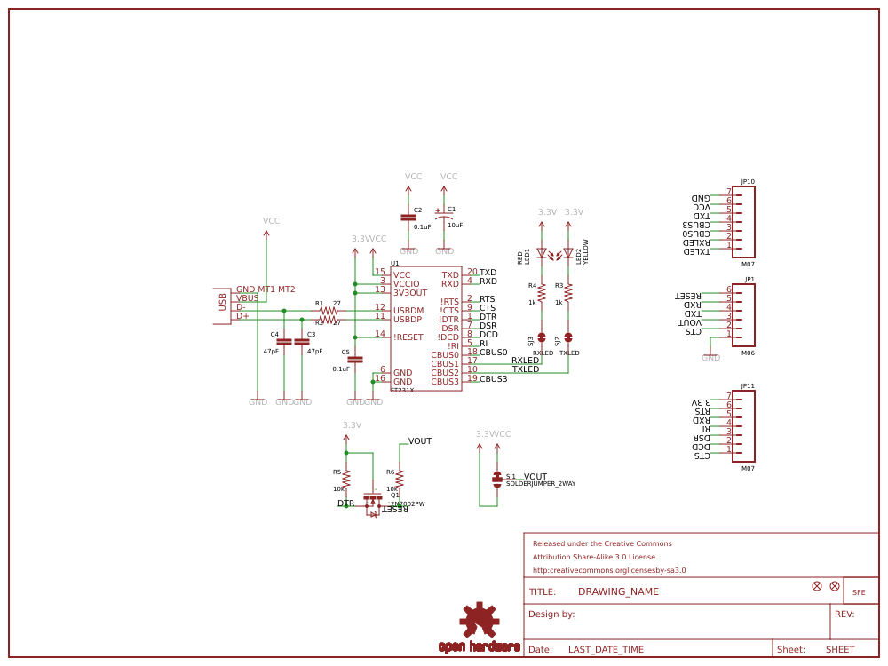
STD FT231X Breakout (Open hardware)。
Mode: Editors' pick
- 1
Update time:
2021-04-09 16:11:18
Creation time:
2015-12-22 02:38:49
Description
Description: Introducing the 3.3V SparkFun FT231X Breakout board, complete with the full UART hardware handshake feature! The pinout of this board matches the FTDI cable to work with official Arduino and cloned 3.3V Arduino boards. It can also be used for general serial applications. This board still brings out the DTR pin as opposed to the RTS pin of the FTDI cable. The DTR pin allows an Arduino target to auto-reset when a new Sketch is downloaded. This is a really nice feature to have and allows a sketch to be downloaded without having to hit the reset button. This board will auto reset any Arduino board that has the reset pin brought out to a 6-pin connector.
The coolest thing about the FT231X Breakout is that we have broken out ALL the pins for your use, making this board all the more hackable! It also uses a common microUSB jack.
One of the features of this board is a jumper on the back, which allows the VCC output to be configured to either 3.3V or 5V. This board ships default to 5V, but you can cut the default trace and add a solder jumper if you need to switch to 3.3V. It should be noted, however, that the max input of the FT231X is only 3.3V but it can operate down to 1.8V with external pull ups and is also 5V tolerant.
[Github Repository][1]
Sparkfun link:https://www.sparkfun.com/products/11736
![enter image description here][2]
[1]: https://github.com/sparkfun/FT231X_Breakout
[2]: /editor/20151231/5684e6780f83d.png
Design Drawing
schematic diagram
(
1
/
)
PCB
(
1
/
)
The preview image was not generated, please save it again in the
editor.
| ID | Name | Designator | Footprint | Quantity |
|---|---|---|---|---|
| 1 | FRAME-LETTER | FRAME1 | CREATIVE_COMMONS | 1 |
| 2 | FT231X | U1 | SSOP20_L | 1 |
| 3 | 0.1uF | C2,C5 | 0402-CAP | 2 |
| 4 | 47pF | C3,C4 | 0402-CAP | 2 |
| 5 | 27 | R1,R2 | 0402-RES | 2 |
| 6 | USB | X1 | USB-MICROB | 1 |
| 7 | M06 | JP1 | 1X06_NS | 1 |
| 8 | SOLDERJUMPER_2WAY | SJ1 | SJ_3 | 1 |
| 9 | 10uF | C1 | EIA3216 | 1 |
| 10 | RED | LED1 | LED-0603 | 1 |
| 11 | YELLOW | LED2 | LED-0603 | 1 |
| 12 | 1k | R3,R4 | 0402-RES | 2 |
| 13 | TXLED | SJ2 | SJ_2S-TRACE | 1 |
| 14 | RXLED | SJ3 | SJ_2S-TRACE | 1 |
| 15 | M07 | JP10,JP11 | 1X07_NS | 2 |
| 16 | 2N7002PW | Q1 | SOT323 | 1 |
| 17 | 10k | R5,R6 | 0402-RES | 2 |
| 18 | LOGO-SFE | JP2 | SFE-NEW-WEB | 1 |
| 19 | OSHW-LOGO | U$1 | OSHW-LOGO-S | 1 |
| 20 | FIDUCIAL | JP3,JP4 | MICRO-FIDUCIAL | 2 |
Unfold
Project Members


 0
0
 1
1
Collect to album
Target complaint
Related Projects
Change a batch
Loading...
Add to album
×
Loading...
reminder
×
Do you need to add this project to the album?