


© 2024 EasyEDA Some rights reserved ISO/IEC
Editor Version
×
Standard

1.Easy to use and quick to get started
2.The process supports design scales of 300 devices or 1000 pads
3.Supports simple circuit simulation
4.For students, teachers, creators
Profession

1.Brand new interactions and interfaces
2.Smooth support for design sizes of over 5,000 devices or 10,000 pads
3.More rigorous design constraints, more standardized processes
4.For enterprises, more professional users

Ongoing
STD MOSFET based Solid-State Relay with Opto-isolated Input
License: Public Domain
Mode: Editors' pick
- 0
Update time:
2020-10-12 15:08:20
Creation time:
2020-09-29 06:09:28
Description
A Solid-State Relay uses a Power Semiconductor like a TRIAC or MOSFET as a switch, eliminating any moving parts, which makes is more reliable compared to it's mechanical counterpart. A mechanical relay may wear out after, say, a hundred thousand switching cycles; a Solid-State Relay can switch any number of times without wear, making it more reliable. In addition to wear due to switching, a mechanical relay can spark at it's contacts; a Solid-State Relay, on the other hand, does not.
This circuit, unlike other MOSFET Relay topologies, offers true input isolation through an optocoupler due to the fact that the required gate voltage is derived from it's own single-diode rectifier power supply and not from the triggering circuit's power supply. I've seen some topologies in which the MOSFET is switched on using an optocoupler, but the power comes from the power supply of the microcontroller. That's not really isolation, in my opinion. This circuit provides true isolation and can be controlled safely using a microcontroller or any other triggering circuit with which a human might interact.
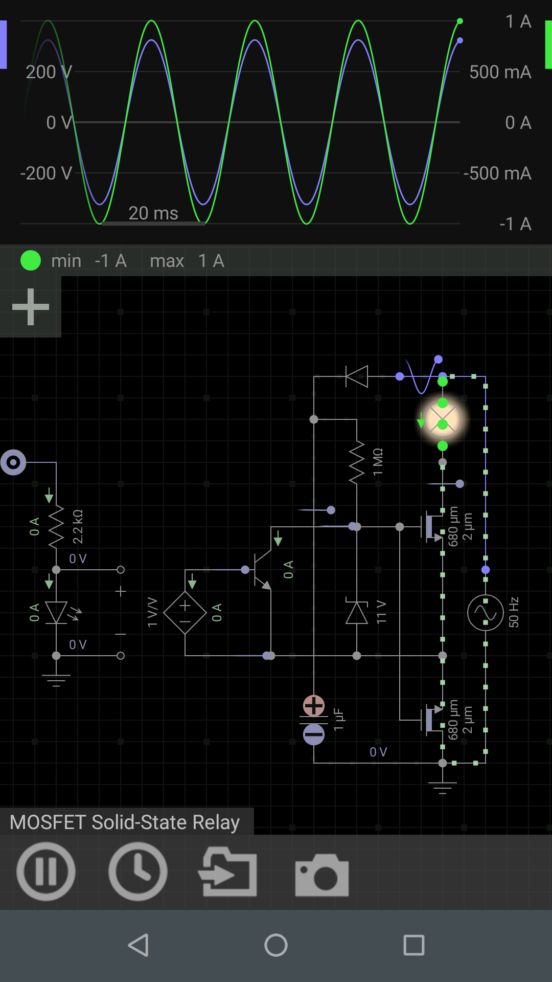
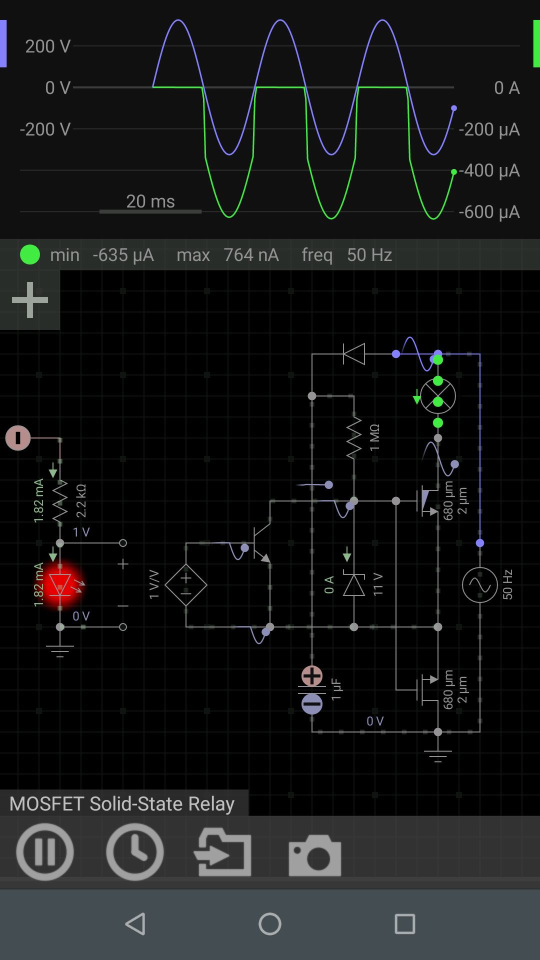
When the AC input turns on, the 0.1uF capacitor starts charging up. For a 0V input to the optocoupler, the NPN transistor stays off, so the MOSFET switch turns on when Vgs(th) is reached and then the zener starts conducting. When the input to the optocoupler is 5V, the optocoupler turns on, bringing the MOSFET's gate voltage very close to the source voltage, turning it off.
Advantages over a TRIAC switch:
-This switch is voltage controlled.
-Since there is no "holding" and "latching" current in a MOSFET, so the switch doesn't have to be repeatedly fired.
Everycircuit Simulation Link: https://everycircuit.com/circuit/5169011642597376 (desktop)
http://everycircuit.com/circuit/5169011642597376 (android app)
Design Drawing
schematic diagram
(
1
/
)
PCB
(
1
/
)
The preview image was not generated, please save it again in the
editor.
| ID | Name | Designator | Footprint | Quantity |
|---|---|---|---|---|
| 1 | 220-240V, 50Hz | MAINS | NONE | 1 |
| 2 | 100nF | U1 | CAP-TH_L10.5-W5.0-P7.50-D1.2 | 1 |
| 3 | 1N4007G_C232439 | D1 | DO-41_BD2.4-L4.7-P8.70-D0.9-RD | 1 |
| 4 | 1M | R1 | R0603 | 1 |
| 5 | 1k | R2,LOAD | R0603 | 2 |
| 6 | IRF740 | Q1,Q2 | TO-220-3_L10.0-W4.5-P2.54-L | 2 |
| 7 | UPC817CG-D04-T | U2 | DIP-4_L4.6-W6.5-P2.54-LS7.6-BL | 1 |
| 8 | 1N4741A | ZD1 | DO-41_BD2.4-L4.7-P8.70-D0.9-RD | 1 |
Unfold
Project Members


 0
0
 0
0
Collect to album
Related Projects
Change a batch
Loading...
Add to album
×
Loading...
reminder
×
Do you need to add this project to the album?