


© 2024 EasyEDA Some rights reserved ISO/IEC
Editor Version
×
Standard

1.Easy to use and quick to get started
2.The process supports design scales of 300 devices or 1000 pads
3.Supports simple circuit simulation
4.For students, teachers, creators
Profession

1.Brand new interactions and interfaces
2.Smooth support for design sizes of over 5,000 devices or 10,000 pads
3.More rigorous design constraints, more standardized processes
4.For enterprises, more professional users
Ongoing
STD Li-Po battery charger
Mode: Editors' pick
- 1
Update time:
2021-04-11 04:20:20
Creation time:
2015-08-30 10:20:26
Description
**Li-Po battery charger.**
--------------------------
**Lithium-Polymer battery**
Li-Po or Lithium polymer battery are batteries based on the lithium -ion technology that are manufactured in a pouch format.The application of pouch format makes them very light but mechanically less rigid. Any way the name comes from the usage of polymer electrolytes instead of lithium salt electrolytes which ware used in its predecessors. The light weight and good current capacity makes them suitable for powering hand held gadgets, RC planes, quad copters, RC toys etc.
Li-Po batteries are susceptable to al problems encoutered by the Lithium ion batteries. overcharging, deep discharging, over heating and short circuit may permanently damage the cell or even cause fire. So great care must me given while using them.
**Working.**
Here we are discussing about a charger for charging a single 3.7V/360mAh Li-Po battery which are commonly used in mini RC planes and quadcopters. A 3.7V li-po battery can be charged up to 4.2 volts and the charging current must be 1/5 the milli ampere hour rating ie; around 72mA.
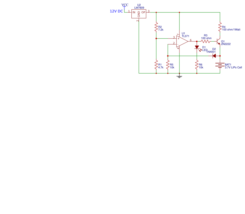
Here we are charging the battery only up to 4 volts for additional safety.The circuit operates from 12v DC supply and disconnects the charging voltage whenthe battery voltage is above 4 volts. TL071 opamp is the heart of this circuit.It is wired as a comparator for monitoring and controlling the charging process. Resistors R1 and R2 set the 3.5V reference for the comparator. Feedback voltage is given to inverting input
of the opamp.
When the battery voltage rises above 4v, the feedback voltage will be above 3.5V (4V-diode D2 drop) and the output of the opamp goeas to negative saturation. This makes the transistor Q1 OFF and the battery is isolated from the charging voltage.When the battery voltage goes below 4V, the voltage at the inverting input goes below 3.5V and the output of the opamp goeas to positive saturation. The transistor is switched on and the battery starts charging. The resistor R4 limits the charging current to around 65mA. R5 is a pull down resistor and R3 limits the base current of Q1. 7809 IC ensures a steady 9V level from the 12V supply. LED D1 is just an indicator. It glows when the battery is being charged and goes of when the battery is fully charged ie; to 4 volts.
![enter image description here][1]
**Circuit diagram.**
[1]: /editor/20150910/55f0622c2d9b5.png
Design Drawing
schematic diagram
(
1
/
)
PCB
(
1
/
)
The preview image was not generated, please save it again in the
editor.
| ID | Name | Designator | Footprint | Quantity |
|---|---|---|---|---|
| 1 | TL071 | U1 | NONE | 1 |
| 2 | 4.7k | R1 | R3 | 1 |
| 3 | 7.2k | R2 | R3 | 1 |
| 4 | 100 ohm | R3 | R3 | 1 |
| 5 | 100 ohm/1Watt | R4 | R3 | 1 |
| 6 | 10k | R5,R6 | R3 | 2 |
| 7 | LED | D1 | LED3MM | 1 |
| 8 | 2N2222 | Q1 | SOT23 | 1 |
| 9 | 1N4001 | D2 | DO35-7 | 1 |
| 10 | 3.7V LiPo Cell | BAT1 | LIPO-1100MAH | 1 |
| 11 | LM7809 | U2 | TO | 1 |
Unfold
Project Members


 0
0
 1
1
Collect to album
Target complaint
Related Projects
Change a batch
Loading...
Add to album
×
Loading...
reminder
×
Do you need to add this project to the album?