


© 2024 EasyEDA Some rights reserved ISO/IEC
Editor Version
×
Standard

1.Easy to use and quick to get started
2.The process supports design scales of 300 devices or 1000 pads
3.Supports simple circuit simulation
4.For students, teachers, creators
Profession

1.Brand new interactions and interfaces
2.Smooth support for design sizes of over 5,000 devices or 10,000 pads
3.More rigorous design constraints, more standardized processes
4.For enterprises, more professional users
Ongoing
STD Clio Main Board
Mode: Editors' pick
- 1
Update time:
2021-04-09 12:59:05
Creation time:
2016-01-12 02:07:40
Description
Clio Main Board
Introduction
An artistic Arduino compatible microcontroller!
Clio is a complete Arduino compatible microcontroller. The former comparatively rigid PCBs are well transformed and take on a brand new vivid outlook with dynamic artistic and design elements into classic Arduino Leonardo version. If you desire for a unique Arduino , Clio would be a great choice.
Why Art Meets Open Hardware?
It’s well known that the major reason of Arduino’s popularity is that it reduces the difficulty in using hardware. This makes it possible for innovators who have no hardware background to build projects easily.
Seeed has been thinking about presenting Arduino to beginners in a more friendly way, so that PCB won’t be prohibitive to them. Hence, an idea that combines arts and Arduino arises spontaneously.
How Art Meets Open Hardware: Clio comes into being!
We invited the famous Chinese illustrator Popil to take part in the design of this product.
The appearance of Clio resembles the Russian Dolls, with electronic elements added, On the premise of functionality and stability, we all adopted SMT components, and tried to reduce the number of components to the least, so that the silkscreen on the back of Clio can be well protected, making the board more concise.
In order to make the doll more vivid, we use the stop mask at the eyes area on PCB. When the LEDs (pins 11 and 13) light up, the bright eyes can be seen even from the front side of the board.
The “Heart” of Clio
The artistic elements and precise design of Clio are based on the same microcontroller as Arduino Leonardo, the ATmega32u4 chip with 3.3 voltages condition.
ATmega32u4 owns 8-bit microprocessor, but the amazing new feature in-build USB Protocol achieves USB serial- communication successfully without ft232! So, you can enjoy a cheaper and more qualified Arduino.
Sharp feature of Clio
Clio is a product for the calling of e-artistic fashions. We design a button lithium battery to afford your masterpiece with one more flexible choice, not only limited with USB charging. You simply putting in a lithium battery of 3.0V, Clio will work immediately.
![enter image description here][1]
Model: ARD04181P
Clio1.jpg Clio2.jpg
Appearance
Clio Main Board is a wearable e-textile technology. There were creatively designed to have large connecting pads to allow them to be sewn into clothing.
It was like a lovely doll which has two eyes and mouth.
![enter image description here][2]
Clio MainBoard.jpg
Because of its chic exterior design, it is also a great choice to use it as a ornament.
Interface Function
![enter image description here][3]
Clio Interface1.jpg
Soldering Instroductions
If you want to use it like an Arduino, for example pluging shield modules onto Clio Main Board, then soldering is necessary. Assuming this is your first soldering project, let’s gather the tools and components to get started.
Tools
Only two basic tools are needed. If you hadn't have them on hand, then you will need to purchase them. They will be used time and again for your soldering projects. So if you have the available funds, choose tools that are well made.
1. Soldering Iron
You will need a basic soldering iron, a base to hold it, and a wet sponge. If possible, a soldering station, as seen in the picture below, is preferable because it includes an iron, a stand, a sponge and a power unit.
2.Solder
Soldering is to DIY electronics what glue is to paper. It uses an alloy to join two metal surfaces together.
Soldering
First, insert a 6pin header into the left headers in the Clio Main Board and 8pin header into the right headers. Now you can firstly solder both ends of the headers to fixed.
6pin and 8pin header.jpg
Then stack the Board on top. Please keep the pins vertically straight. Make sure the tip of your soldering iron is shiny.
If not, melt some solder on it and quickly wipe it with the wet sponge. Place the solder against the lead you want to solder.
Move the tip of soldering iron to the lead and melt the solder. The melted solder should instantly stick to the lead. If not, use the iron tip to draw it there. When finished, it should resemble a volcano in shape and have a shiny surface. If not, wait for the solder to cool and melt the solder again.
![enter image description here][6]
Solder headers.JPG
Insert two 3pin headers into its given location, maked ISP in the Clio main board and began to solder. After completing the solder, you can plug shield modules into it.
![enter image description here][7]
ISP Header.jpg
Summary
Items parameter
Micro controller ATmega32U4
Operating Voltage 3.0-5.0V
Digital I/O Pins 20 (of which 7 provide PWM output)
Analog Input Pins 12
DC Current per I/O Pin 40 mA
Flash Memory 32 KB (of which 4 KB used by bootloader)
EEPROM 1K
Clock Speed 16 MHz
Input and Output Pin Description
Each of the 20 digital i/o pins on the Clio Main Board can be used as an input or output, using pinMode(), digitalWrite(), and digitalRead() functions.
They operate at 5 volts. Each pin can provide or receive a maximum of 40 mA and has an internal pull-up resistor (disconnected by default) of 20-50 kOhms.
In addition, some pins have specialized functions:
Serial: 0 (RX) and 1 (TX).
Used to receive (RX) and transmit (TX) TTL serial data using the ATmega32U4 hardware serial capability.
Note that on the Leonardo, the Serial class refers to USB (CDC) communication; for TTL serial on pins 0 and 1, use the Serial1 class.
TWI: 2 (SDA) and 3 (SCL).
Support TWI communication using the Wire library.
External Interrupts: 2 and 3.
These pins can be configured to trigger an interrupt on a low value, a rising or falling edge, or a change in value. See the attachInterrupt() function for details.
PWM: 3, 5, 6, 9, 10, 11, and 13.
Provide 8-bit PWM output with the analogWrite() function.
SPI: on the ICSP header.
These pins support SPI communication using the SPI library.
Note: that the SPI pins are not connected to any of the digital I/O pins as they are on the Uno, They are only available on the ICSP connector. This means that if you have a shield that uses SPI, but does NOT have a 6-pin ICSP connector that connects to the Leonardo's 6-pin ICSP header, the shield will not work.
LED: 13.
There is a built-in LED connected to digital pin 13. When the pin is HIGH value, the LED is on, when the pin is LOW, it's off.
Analog Inputs: A0-A5, A6 - A11 (on digital pins 4, 6, 8, 9, 10, and 12).
The Clio Main Board has 12 analog inputs, labeled A0 through A11, all of which can also be used as digital i/o. Pins A0-A5 appear in the same locations as on the Seeeduino; inputs A6-A11 are on digital i/o pins 4, 6, 8, 9, 10, and 12 respectively. Each analog input provide 10 bits of resolution (i.e. 1024 different values).
By default the analog inputs measure from ground to 5 volts, though is it possible to change the upper end of their range using the AREF pin and the analogReference() function.
There are a couple of other pins on the board:
AREF. Reference voltage for the analog inputs. Used with analogReference().
Reset. Bring this line LOW to reset the microcontroller. Typically used to add a reset button to shields which block the one on the board.
Communication
The Clio Main Board has a number of facilities for communicating with a computer, another Arduino, or other microcontrollers.
The ATmega32U4 provides UART TTL (5V) serial communication, which is available on digital pins 0 (RX) and 1 (TX).
The 32U4 also allows for serial (CDC) communication over USB and appears as a virtual com port to software on the computer.
The chip also acts as a full speed USB 2.0 device, using standard USB COM drivers.
The Arduino software includes a serial monitor which allows simple textual data to be sent to and from the Arduino board.
The RX and TX LEDs on the board will flash when data is being transmitted via the USB connection to the computer (but not for serial communication on pins 0 and 1).
Get start with Clio Main Board
Hardware Installation
To connect the Clio Main Board to your computer, you'll need a Micro-B USB cable. This USB cable provides power and data to the board.
The first time you plug a Clio Main Board into a PC, the "Does not recognize the USB device" will launch.
Please right click and choose update driver.
programming
Typically, you'll upload program to the Clio Main Board as you do with other Arduino boards: select "Seeeduino Clio" from the Tools > Board menu and the appropriate serial port from the Tools > Serial Port menu.
Click the upload button in the Arduino IDE and your sketch will be automatically uploaded onto the board and then started.
[1]: /editor/20160112/56946088d2631.png
[2]: /editor/20160112/56946093f0c3d.png
[3]: /editor/20160112/569460a186961.png
[4]: /editor/20160112/569460ae1ced6.png
[5]: /editor/20160112/569460b64d501.png
[6]: /editor/20160112/569460e8a1582.png
[7]: /editor/20160112/569460f7bbc96.png
Design Drawing
schematic diagram
(
1
/
)
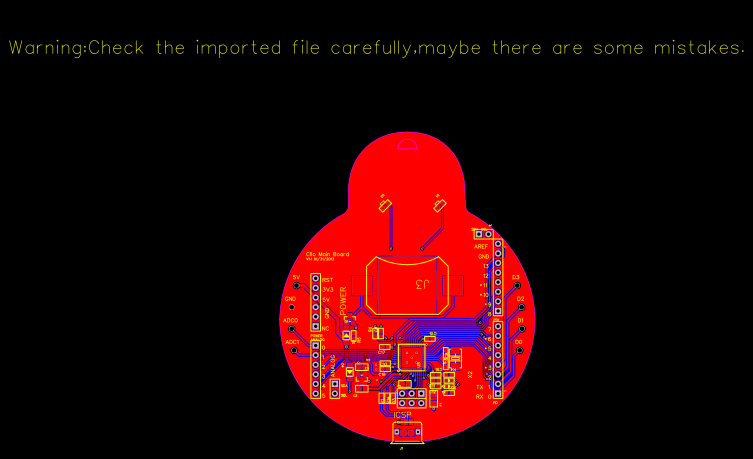
PCB
(
1
/
)
The preview image was not generated, please save it again in the
editor.
| ID | Name | Designator | Footprint | Quantity |
|---|---|---|---|---|
| 1 | XC6206P332MR-G | U3 | SOT23 | 1 |
| 2 | 10uF | C3,C4 | C0805 | 2 |
| 3 | 22R | R1,R14,R6,R7 | R0603 | 4 |
| 4 | 1uF | C1 | C0805 | 1 |
| 5 | 2.54-2x3p male | ICSP | 2X3P-2.54 | 1 |
| 6 | 2.54-6p female | ANALOG,POWER | 6P-2.54-6535MIL | 2 |
| 7 | 2.54-8p female | PD,PD1 | 8P-2.54 | 2 |
| 8 | 16MHz | X2 | 2P-SMD-5X3.2 | 1 |
| 9 | 22pF | C8,C9 | C0603 | 2 |
| 10 | 10k | R3,R5 | R0603 | 2 |
| 11 | 100nF | C10,C12,C15,C16,C17,C18 | C0603 | 6 |
| 12 | Atmega32U4 | U5 | QFN44 | 1 |
| 13 | RED | TX,RX | LED-0603 | 2 |
| 14 | 1k | R2,R4 | R0603 | 2 |
| 15 | 10nF | C11 | C0603 | 1 |
| 16 | USB-MICRO-5P | J1 | MICRO-USB-5P | 1 |
| 17 | pptc-500mA | F1 | F1206 | 1 |
| 18 | CR2032-172 | J3 | 2032-SMD-D20.32 | 1 |
| 19 | side-WHITE | D1,D2 | LED-SIDE-VIEW-0603-RIGHT | 2 |
| 20 | DNP | J4,J2 | 2P-2.54-6535MIL | 2 |
| 21 | SS0520-7-F | D3,D4 | SOD123 | 2 |
| 22 | si2305DS | Q1 | SOT23 | 1 |
Unfold
Project Members


 0
0
 1
1
Collect to album
Target complaint
Related Projects
Change a batch
Loading...
Add to album
×
Loading...
reminder
×
Do you need to add this project to the album?