


© 2024 EasyEDA Some rights reserved ISO/IEC
Editor Version
×
Standard

1.Easy to use and quick to get started
2.The process supports design scales of 300 devices or 1000 pads
3.Supports simple circuit simulation
4.For students, teachers, creators
Profession

1.Brand new interactions and interfaces
2.Smooth support for design sizes of over 5,000 devices or 10,000 pads
3.More rigorous design constraints, more standardized processes
4.For enterprises, more professional users
Ongoing
STD Grove - Green LED
Mode: Editors' pick
- 0
Update time:
2022-01-17 05:48:57
Creation time:
2016-01-14 02:28:40
Description
Grove - Green LED
-----------------
![enter image description here][1]
A general purpose LED module in Grove form factor, available in different colors.
The ingenious PCB design enables you to bend the LED to any position you want, which makes it easy to use it standalone, horizontal or Panel Mount(from left to right in below pics)
Specification
Standard Grove connector
Operate voltage: 3.3v/5v
Emitting Color: Green
For all Grove users (especially beginners), we provide you guidance PDF documents. Please download and read through Preface - Getting Started and Introduction to Grove before your using of the product.
Features
Grove compatible interface
3.3V/5V Compatible
Adjustable LED orientation
Adjustable LED brightness
Specification
Item Description
LED Control Mode Digital Pin of Arduino
Working Voltage 5V
Supply Mode Grove Interface
Usage :
With Arduino
------------
Here we show how to use Arduino to control the state of the LED.
1. Connect the LED to Base Shield's digital port 2 with 4pin Grove Cable.Of course you can change to other valid digital ports if it's necessary and the definitions of the port should be changed too.
2. Plug it onto the Arduino/Seeeduino. Connect the board to PC using USB cable.
![![enter image description here][2]][3]
3. Copy the demo code to your sketch, then upload to Arduino or Seeeduino board. Please click here if you do not know how to upload.
You will see the LED blink every second.
/************************* 2012 Seeedstudio **************************
* File Name : GroveLEDDemoCode.ino
* Author : Seeedteam
* Version : V1.1
* Date : 18/2/2012
* Description : Demo code for Grove - LED
*************************************************************************/
#define LED 2 //connect LED to digital pin2
void setup() {
// initialize the digital pin2 as an output.
pinMode(LED, OUTPUT);
}
void loop() {
digitalWrite(LED, HIGH); // set the LED on
delay(500); // for 500ms
digitalWrite(LED, LOW); // set the LED off
delay(500);
}
With Rasberry Pi:
-----------------
Connect the LED to Port D4 and power on the Raspberry Pi, using the Grove wire connector. This is a test to make led blinking. You can connect to GrovePi+ with it as the picture below.
![enter image description here][4]
# GrovePi LED Blink example
import time
from grovepi import *
# Connect the Grove LED to digital port D4
led = 4
pinMode(led,"OUTPUT")
time.sleep(1)
while True:
try:
#Blink the LED
digitalWrite(led,1) # Send HIGH to switch on LED
time.sleep(1)
digitalWrite(led,0) # Send LOW to switch off LED
time.sleep(1)
except KeyboardInterrupt: # Turn LED off before stopping
digitalWrite(led,0)
break
except IOError: # Print "Error" if communication error encountered
print "Error"
Run The Program
Find the path to the file(According to your own path)
cd GrovePi/Software/Python/
Run Program
sudo python grove_led_blink.py
From:For more detail, please visit: http://www.seeedstudio.com/item_detail.html?p_id=1144
[1]: http://www.seeedstudio.com/depot/bmz_cache/f/f27040ee3d12783bbf6490a99ca1512e.image.530x397.jpg
[2]: http://www.seeedstudio.com/wiki/images/thumb/0/0e/Grove-LED.jpg/500px-Grove-LED.jpg
[3]: http://www.seeedstudio.com/wiki/images/thumb/0/0e/Grove-LED.jpg/500px-Grove-LED.jpg
[4]: /editor/20160114/569709a2d255b.png
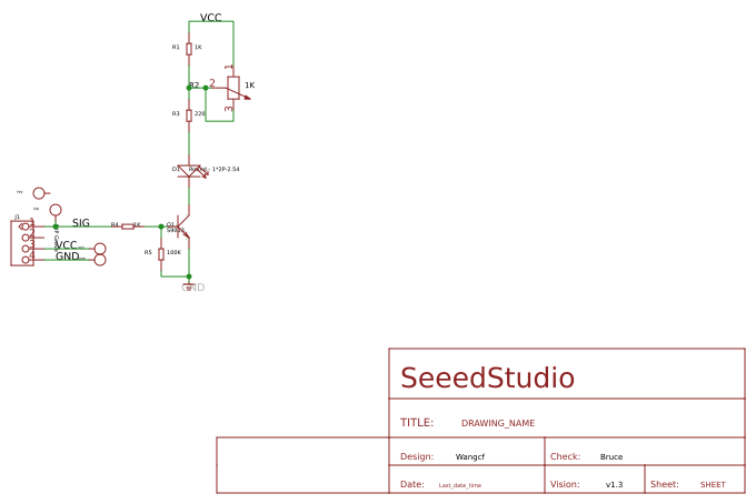
Design Drawing
schematic diagram
(
1
/
)
PCB
(
1
/
)
The preview image was not generated, please save it again in the
editor.
| ID | Name | Designator | Quantity |
|---|---|---|---|
| 1 | SEEEDSTUDIO_SCH_FRAME | U$1 | 1 |
| 2 | 1K | R1,R4 | 2 |
| 3 | DIP Grove | J1 | 1 |
| 4 | Round - 1*2P-2.54 | D1 | 1 |
| 5 | 1K | R2 | 1 |
| 6 | 220 | R3 | 1 |
| 7 | PAD-TEST-POINT | SIG,TP2,GND,VCC | 4 |
| 8 | S9013 | Q1 | 1 |
| 9 | 100K | R5 | 1 |
Unfold
Project Members


 0
0
 0
0
Collect to album
Target complaint
Related Projects
Change a batch
Loading...
Add to album
×
Loading...
reminder
×
Do you need to add this project to the album?