


© 2024 EasyEDA Some rights reserved ISO/IEC
Editor Version
×
Standard

1.Easy to use and quick to get started
2.The process supports design scales of 300 devices or 1000 pads
3.Supports simple circuit simulation
4.For students, teachers, creators
Profession

1.Brand new interactions and interfaces
2.Smooth support for design sizes of over 5,000 devices or 10,000 pads
3.More rigorous design constraints, more standardized processes
4.For enterprises, more professional users
Ongoing
STD Motor Bridge Cape
Mode: Editors' pick
- 0
Update time:
2021-04-10 01:28:10
Creation time:
2016-01-09 05:47:16
Description
Description
Motor Bridge Cape
The Motor Bridge Cape features bi-directional motor control using two TB6612FNG integrated dual H-bridge, so it can control two stepper motors or four brushed DC motors with 6~15V DC power and about 1A current draw per motor. The cape provides 5V regulated power to BBG or BBB with a max input voltage of 15V. It also has six servo control interface and six expand IO. All the features are provided by the on board STM32F0 coprocessor. The coprocessor can communicate with BeagleBone by I2C or UART interface.
![enter image description here][1]
Features
Can drive 4 DC Motors or 2 Stepper Motors
Can drive 6 Servos
Mbed Platform
STM32F0 coprocessor
Two TB6612FNG
6 expand IOs
Communicate with BBG by I2C or UART interface
Specification
Battery Input Voltage: 6~15V
H-bridge Working Voltage: 6~15V
DC/DC 5V output current: 2A max
3V3 output current: 350mA max
4 H-bridge driver,each rated current:1.2A, peak current:3.2A
6 Servo driver, working voltage: 5V, total current is not more than 1.5A
Input reverse connect protection
Over current protection: 3A one-off quick fuse
Basic Demo
Basic Demo
![enter image description here][2]
It is a demo which we connect Motor Bridge Cape with BBG to drive 1 Stepper Motor, 2 DC Motors and 6 Servos at the same time.
From :For more detail, please visit: http://www.seeedstudio.com/item_detail.html?p_id=2569?cPath=122_113
[1]: /editor/20160109/56909f03100d7.png
[2]: /editor/20160109/56909f0e02117.png
Design Drawing
schematic diagram
(
1
/
)
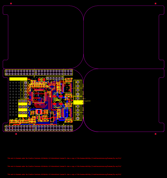
PCB
(
1
/
)
The preview image was not generated, please save it again in the
editor.
| ID | Name | Designator | Footprint | Quantity |
|---|---|---|---|---|
| 1 | TB6612FNG | U2,U1 | SSOP24-0.65-8.3X5.6MM | 2 |
| 2 | 47uF 25V | C1,C26 | ELECTRO-SMD-C-6MM | 2 |
| 3 | BAT | J1 | H2-3.5-7.0X7.0MM | 1 |
| 4 | 10uF 25V | C5,C6,C11,C12 | C0805 | 4 |
| 5 | 100nF | C7,C8,C19,C20,C21,C22,C24,C3,C25,C27,C28,C2,C4,C32,C13,C14 | C0603 | 16 |
| 6 | 100K | R2,R7,R19 | R0603 | 3 |
| 7 | 47K | R3 | R0603 | 1 |
| 8 | 51k_1% | R6 | R0603 | 1 |
| 9 | 22nF | C9 | C0603 | 1 |
| 10 | 15pF | C10 | C0603 | 1 |
| 11 | PMV31XN | Q1 | SOT-23 | 1 |
| 12 | 8M | X1 | X2-SMD-5.0X3.2X1.3MM | 1 |
| 13 | 390R | R8 | R0603 | 1 |
| 14 | 20pF | C15,C16 | C0603 | 2 |
| 15 | 10uF | C17,C23,C29,C30,C31,C33 | C0603 | 6 |
| 16 | 10nF | C18 | C0603 | 1 |
| 17 | SW4P | K1 | SW4P-SMD-4.5X3.2X2.5MM | 1 |
| 18 | 3.3k | R10,R11,R12,R13,R14,R15,R16,R17,R18,R23,R22,R24 | R0603 | 12 |
| 19 | Debug | J5 | H6-2.54-C65D35MIL | 1 |
| 20 | red | D1,D3,D5,D7 | LED-0603 | 4 |
| 21 | blue | D2,D4,D6,D8 | LED-0603 | 4 |
| 22 | 330R | FB1,FB2,FB3,FB6,FB5,FB4 | L0603 | 6 |
| 23 | HEADER-6P | J2,J7,J10 | H6-2.54-C65D35MIL | 3 |
| 24 | 3V3 DNP | J3 | H6-2.54-C65D35MIL | 1 |
| 25 | IO DNP | J12 | H6-2.54-C65D35MIL | 1 |
| 26 | 33k | R20,R4 | R0603 | 2 |
| 27 | 0R | R21 | R0603 | 1 |
| 28 | Green | PWR | LED-0603 | 1 |
| 29 | 1N4148WT | D10,D9 | SOD-523 | 2 |
| 30 | BBCN | J8,J9 | 2X23P-2.54 | 2 |
| 31 | MP1496 | U4 | SOT-23-8 | 1 |
| 32 | 10R | R1 | R0603 | 1 |
| 33 | 270K_1% | R5 | R0603 | 1 |
| 34 | SEEEDSTUDIO-OPEN-SCH-FRAME | FR1,FR2,FR4 | SEEEDSTUDIO-PCB-FRAME | 3 |
| 35 | 1M | R9 | R0603 | 1 |
| 36 | MOTO | J4,J6 | H4-3.5-14.0X7.0MM | 2 |
| 37 | 0467003.NRHF | F1,F2 | R0603 | 2 |
| 38 | STBY | SW1 | SW7-SMD-L6.7X2.7X3.2MM | 1 |
| 39 | STM32F030R8 | U3 | LQFP64-0.5-10X10MM | 1 |
| 40 | 10uH | L2 | L1813 | 1 |
| 41 | MARK-1.0 | P1,P2,P3,P4,P5,P6,P7,P8 | ROUND-MARK-1.0 | 8 |
Unfold
Project Members


 0
0
 0
0
Collect to album
Target complaint
Related Projects
Change a batch
Loading...
Add to album
×
Loading...
reminder
×
Do you need to add this project to the album?