


© 2024 EasyEDA Some rights reserved ISO/IEC
Editor Version
×
Standard

1.Easy to use and quick to get started
2.The process supports design scales of 300 devices or 1000 pads
3.Supports simple circuit simulation
4.For students, teachers, creators
Profession

1.Brand new interactions and interfaces
2.Smooth support for design sizes of over 5,000 devices or 10,000 pads
3.More rigorous design constraints, more standardized processes
4.For enterprises, more professional users
Ongoing
STD Raspberry Pi Motor Driver Board v1.0
Mode: Editors' pick
- 0
Update time:
2021-04-11 13:53:38
Creation time:
2016-01-08 11:41:30
Description
![enter image description here][1]
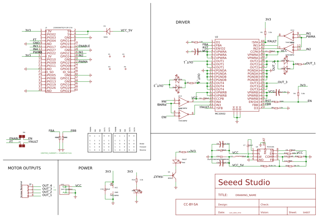
Raspberry Pi Motor Driver Board v1.0 is based on the Freescale MC33932 dual H-Bridge Power IC, which can control inductive loads with currents up to 5.0A peak per single bridge.
It lets you drive two DC motors with your Raspberry Pi B/B+/A+ and Pi 2 Model B, controlling the speed and direction of each one independently.
Raspberry Pi Motor Driver Board v1.0 support a very wide range of input voltage from 6V~28V. otherwise ,the on board DC/DC converter support a very wide range of input voltage, and can provide a 5V power supply for the Raspberry Pi with 1000mA maximum current.
So, you just need one power supply to drive the motors and power up the Raspberry Pi.
Features:
Operating Voltage: 6V ~ 28V
DC/DC output: 5V 1000mA @ "5V" pin
Output Current(For Each Channel ): 2A (continuous operation) / 5A(peak)
Output Duty Range: 0%~100%
Output short-circuit protection (short to VPWR or GND)
Over-current limiting (regulation) via internal constant-off-time PWM
Temperature dependant current limit threshold reduction
Raspberry Pi compatible
Compatible:Raspberry Pi ; Other main board via jumpers;
Power interface:DC Jack;
Dimensions:91.20 * 56.15mm;
Operating Voltage: 6V ~ 28V
From: For more detail, please visit: http://www.seeedstudio.com/item_detail.html?p_id=2411?cPath=122_154_158
Introduction
Raspberry Pi Motor Driver Board v1.0 is based on the Freescale MC33932 dual H-Bridge Power IC, which can control inductive loads with currents up to 5.0A peak per single bridge. It lets you drive two DC motors with your Raspberry Pi B/B+/A+ and Pi 2 Model B, controlling the speed and direction of each one independently.
Raspberry Pi Motor Driver Board v1.0 support a very wide range of input voltage from 6V~28V. otherwise ,the on board DC/DC converter support a very wide range of input voltage, and can provide a 5V power supply for the Raspberry Pi with 1000mA maximum current. So, you just need one power supply to drive the motors and power up the Raspberry Pi.
Features
Output short-circuit protection (short to VPWR or GND)
Over-current limiting (regulation) via internal constant-off-time PWM
Temperature dependant current limit threshold reduction
Raspberry Pi compatible
Specification
Item Min Typical Max Unit
Operating Voltage 6 / 28 VDC
DC/DC output: / 5V/1000mA /
Output Current(For Each Channel ) / 2 (continuous operation) 5 (peak) A
PWM Frequency / / 11 kHz
Output Duty Range 0 / 100 %
Logic Input Voltage -0.3 / 7 V
Operating Temperature -40 / 120 ℃
Dimension 91.20 * 56.15*32 mm
Interface Function
![enter image description here][2]
J1:DC Input connector.
J2:Motor Driver output connector.
EN,FT:Jumpers for EN control and Fault flag detection.If short circuit the EN jumper, the EN signal was mapped to the D4 pin ,you can control the H-Bridge disable output or reset the Fault flag by D4 pin.
If short circuit the FT jumper, the fault flag signal was mapped to D3 pin ,you can read the fault flag from the D3 pin ether.
IO:Logic Voltage level Select Jumper. You can choose the control logic voltage level from this jumper.
Power Supply: You have to power up the shield from the J1(DC input connector).The input voltage range can be set up to 6Vdc ~ 28Vdc.The on board DC/DC converter can convert the DC input voltage to 5Vdc output voltage to supply the logic circuit.The DC/DC converter can also power up the microcontroller board(Arduino/Seeeduino) form "5V" pin for maximun 100mA current.
Motor Interface:Out 1 and Out 2(Out 3 and Out 4) connect Motor A(B) for DC Motor.
Caution
Do not touch the H-bridge IC or PCB board during working. Its temperature can reach up to 100 degrees in the case of full load operating.
Usage
This demo is using Raspberry Pi B to show that Raspberry Pi Motor Driver Board v1.0 be use to control DC motor forward and backward.
Hardware Installation
1) Raspberry Pi B & Raspberry Pi Motor Driver Board v1.0
2) Hardware connection as shown connect to network and power
![enter image description here][3]
Software Part
1) Copy these code as follows;
#!/usr/bin/python
import RPi.GPIO as GPIO
import time
import signal
from PiSoftPwm import *
#print 'Go_1...'
#frequency = 1.0 / self.sc_1.GetValue()
#speed = self.sc_2.GetValue()
class Motor():
def __init__(self):
# MC33932 pins
self.PWMA = 25
self.PWMB = 22
self._IN1 = 23
self._IN2 = 24
self._IN3 = 17
self._IN4 = 27
# Initialize PWMA PWMB
GPIO.setmode(GPIO.BCM)
GPIO.setup(self.PWMA, GPIO.OUT)
GPIO.setup(self.PWMB, GPIO.OUT)
GPIO.output(self.PWMA, True)
GPIO.output(self.PWMB, True)
# Initialize PWM outputs
self.OUT_1 = PiSoftPwm(0.1, 100, self._IN1, GPIO.BCM)
self.OUT_2 = PiSoftPwm(0.1, 100, self._IN2, GPIO.BCM)
self.OUT_3 = PiSoftPwm(0.1, 100, self._IN3, GPIO.BCM)
self.OUT_4 = PiSoftPwm(0.1, 100, self._IN4, GPIO.BCM)
# Close pwm output
self.OUT_1.start(0)
self.OUT_2.start(0)
self.OUT_3.start(0)
self.OUT_4.start(0)
self.frequency = 0.01
self.duty = 60
def Setting(self, frequency, duty):
self.frequency = frequency
self.duty = duty
def Go_1(self):
self.OUT_1.changeBaseTime(self.frequency)
self.OUT_2.changeBaseTime(self.frequency)
self.OUT_1.changeNbSlicesOn(self.duty)
self.OUT_2.changeNbSlicesOn(0)
def Back_1(self):
self.OUT_1.changeBaseTime(self.frequency)
self.OUT_2.changeBaseTime(self.frequency)
self.OUT_1.changeNbSlicesOn(0)
self.OUT_2.changeNbSlicesOn(self.duty)
def Go_2(self):
self.OUT_3.changeBaseTime(self.frequency)
self.OUT_4.changeBaseTime(self.frequency)
self.OUT_3.changeNbSlicesOn(0)
self.OUT_4.changeNbSlicesOn(self.duty)
def Back_2(self):
self.OUT_3.changeBaseTime(self.frequency)
self.OUT_4.changeBaseTime(self.frequency)
self.OUT_3.changeNbSlicesOn(self.duty)
self.OUT_4.changeNbSlicesOn(0)
def Stop():
self.OUT_1.changeNbSlicesOn(0)
self.OUT_2.changeNbSlicesOn(0)
self.OUT_3.changeNbSlicesOn(0)
self.OUT_4.changeNbSlicesOn(0)
if __name__=="__main__":
motor=Motor()
# Called on process interruption. Set all pins to "Input" default mode.
def endProcess(signalnum = None, handler = None):
motor.OUT_1.stop()
motor.OUT_2.stop()
motor.OUT_3.stop()
motor.OUT_4.stop()
motor.GPIO.cleanup()
exit(0)
# Prepare handlers for process exit
signal.signal(signal.SIGTERM, endProcess)
signal.signal(signal.SIGINT, endProcess)
signal.signal(signal.SIGHUP, endProcess)
signal.signal (signal.SIGQUIT, endProcess)
motor.Setting(0.01, 60)
print 'motor start...'
while True:
print 'turning direction...'
motor.Go_1()
time.sleep(1)
motor.Back_1()
time.sleep(1)
motor.Go_2()
time.sleep(1)
motor.Back_2()
time.sleep(1)
2) Saved in the Raspberry Pi, According to your own path
3) Run this program,LED1,LED2 on Raspberry Pi Motor Driver Board v1.0 will Alternate lights up,LED3,LED4 is also. it means Out 1 and Out 2(Out 3 and Out 4) connect Motor A(B) forward and back.
4) You can see phenomemon as follows:
serial console:
![enter image description here][4]
Raspberry Pi Motor Driver Board v1.0:
Green LED and Blue LED alternate lights up
![enter image description here][5]
From:http://www.seeedstudio.com/wiki/Raspberry_Pi_Motor_Driver_Board_v1.0
[1]: /editor/20160108/568fa15d9438a.png
[2]: /editor/20160108/568fa1de68f47.png
[3]: /editor/20160108/568fa208bbab1.png
[4]: /editor/20160108/568fa24470d73.png
[5]: /editor/20160108/568fa258e7bf9.png
Design Drawing
schematic diagram
(
1
/
)
PCB
(
1
/
)
The preview image was not generated, please save it again in the
editor.
| ID | Name | Designator | Footprint | Quantity |
|---|---|---|---|---|
| 1 | Screw Terminal | J2 | 4P-3.5 | 1 |
| 2 | Blue | LED4,LED2 | LED-0603 | 2 |
| 3 | Green | LED3,PWR,LED1 | LED-0603 | 3 |
| 4 | 3.3k | R5,R10,R3,R9,R1,R18,R2 | R0603 | 7 |
| 5 | MC33932 | U2 | HSOP44 | 1 |
| 6 | 100uF-35V | C1,C3,C8 | ELECTRO-SMD-E-7.8MM | 3 |
| 7 | 100nF | C2,C4,C15,C9,C7,C16 | C0603 | 6 |
| 8 | 74HC08PW | U3 | TSSOP14 | 1 |
| 9 | Red | FAULT | LED-0603 | 1 |
| 10 | 200R | R11,R12,R17 | R0603 | 3 |
| 11 | PAD-JUMPER-2P | EN,FT | 2P-SMD-1.78X1.27 | 2 |
| 12 | [320030075]2*13P-2.54 | J3 | 2X20P-2.54-6535MIL | 1 |
| 13 | 8550 | Q1 | SOT-23 | 1 |
| 14 | TD1519A | U4 | SOP8-WHEAT | 1 |
| 15 | 10uH | L1 | L0630 | 1 |
| 16 | 220uF-16V | C14 | ELECTRO-SMD-D-5.6MM | 1 |
| 17 | 10uFCC0603KRX5R6BB106 | C11 | C0603 | 1 |
| 18 | 16k 1% | R16 | R0603 | 1 |
| 19 | 76.8k 1% | R15 | R0603 | 1 |
| 20 | 100k | R13 | R0603 | 1 |
| 21 | 3.3nF | C12 | C0603 | 1 |
| 22 | 5.6k | R14,R4 | R0603 | 2 |
| 23 | DNP | C13 | C0603 | 1 |
| 24 | Jack DC-044-A | J13 | DC-044 | 1 |
| 25 | SS54 | D1 | DO_214AA | 1 |
| 26 | PAD-MARK | P1,P2,P3,P4 | ROUND-MARK-1.0 | 4 |
| 27 | SEEEDSTUDIO-OPEN-SCH-FRAME | U$12 | SEEEDSTUDIO-PCB-FRAME | 1 |
Unfold
Project Members


 0
0
 0
0
Collect to album
Target complaint
Related Projects
Change a batch
Loading...
Add to album
×
Loading...
reminder
×
Do you need to add this project to the album?