


© 2024 EasyEDA Some rights reserved ISO/IEC
Editor Version
×
Standard

1.Easy to use and quick to get started
2.The process supports design scales of 300 devices or 1000 pads
3.Supports simple circuit simulation
4.For students, teachers, creators
Profession

1.Brand new interactions and interfaces
2.Smooth support for design sizes of over 5,000 devices or 10,000 pads
3.More rigorous design constraints, more standardized processes
4.For enterprises, more professional users
Ongoing
STD Seeeduino Ethernet
Mode: Editors' pick
- 10
Update time:
2023-11-08 17:27:20
Creation time:
2016-01-12 02:21:12
Description
Introduction
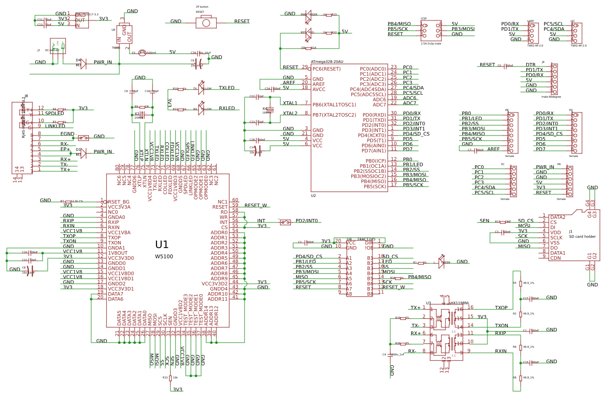
Seeeduino Ethernet is a compact and multifunctional development platform, which merges data logging and processing, device control and Ethernet communication together into one. It's armed with a MEGA328P chip and a Wiz5100: the former provides an Arduino controlling style and the latter provides TCP and UDP Ethernet communication ability. Plus integrated SD card module, it's convenient and neat for remote data logging, processing or transferring via network. In this version, we lowered the height of RJ45 to balance it with the headers. Besides, with an I2C and a UART Grove port populated,it's convenient to connect corresponding Grove modules to this board.4
![enter image description here][1]
Specification
Voltage: 6.2-13V
Current: 140-550mA
Supported Card Type: Micro SD card(must be SanDisk), FAT/FAT32 (More than 2G is not guaranteed)
Supported Connection: TCP/UDP
Net Weight: 23±2g
Ethernet jack: Standard RJ45
Demonstration
We will test the Seeeduino Ethernet functions of writing or reading information from the SD Card and sending out A/D data to network.
![enter image description here][2]
Step 1: Install the Hardware
Firstly, install the hardware. We have two alternatives to plug in the power.
Method 1: You can use one Passive PoE Cable Set to provide power and Ethernet connection at the same time like the picture below.
![enter image description here][3]
Method 2: Use separate power cable and Ethernet cable.
![enter image description here][4]
Step 2: Programing
After hardware installation, here we continue to try the test code. This program is written to test the functions of writing or reading data from the SD Card and sending out A/D data to network. This demo code can be used as a test program as well as reference if you wanna explore more functions of the board.
NOTICE:
1. All the ".h" file needed have been pre-installed in Arduino IDE(1.0).
2. Install a Micro SD card. Make sure the Micro SD card is not full and the format is FAT or FAT32.
/*
SD card read/write
This example shows how to read and write data to and from an SD card file
The circuit:
* SD card attached to SPI bus as follows:
** MOSI - pin 11
** MISO - pin 12
** CLK - pin 13
** CS - pin 4
Web Server
A simple web server that shows the value of the analog input pins.
using an Arduino Wiznet Ethernet shield.
Circuit:
* Ethernet shield attached to pins 10, 11, 12, 13
* Analog inputs attached to pins A0 through A5 (optional)
created 18 Dec 2009
by David A. Mellis
modified 4 Sep 2010
by Tom Igoe
*/
#include
#include
#include
// Enter a MAC address and IP address for your controller below.
// The IP address will be dependent on your local network:
byte mac[] = { 0xDE, 0xAD, 0xBE, 0xEF, 0xFE, 0xED };
IPAddress ip(192,168,1,177);
// Initialize the Ethernet server library
// with the IP address and port you want to use
// (port 80 is default for HTTP):
EthernetServer server(80);
File myFile;
void setup()
{
Serial.begin(9600);
Serial.print("Initializing SD card...");
// On the Ethernet Shield, CS is pin 4. It's set as an output by default.
// Note that even if it's not used as the CS pin, the hardware SS pin
// (10 on most Arduino boards, 53 on the Mega) must be left as an output
// or the SD library functions will not work.
pinMode(10, OUTPUT);
// pinMode(4,OUTPUT);
if (!SD.begin(4)) {
Serial.println("initialization failed!");
return;
}
Serial.println("initialization done.");
// open the file. note that only one file can be open at a time,
// so you have to close this one before opening another.
myFile = SD.open("test.txt",FILE_WRITE);
// if the file opened or created okay, write to it:
if (myFile) {
Serial.print("Writing to test.txt...");
myFile.println("testing 1, 2, 3.");
// close the file:
myFile.close();
Serial.println("done.");
} else {
// if the file didn't open, print an error:
Serial.println("error opening test.txt");
}
// re-open the file for reading:
myFile = SD.open("test.txt");
if (myFile) {
Serial.println("test.txt:");
// read from the file until there's nothing else in it:
while (myFile.available()) {
Serial.write(myFile.read());
}
// close the file:
myFile.close();
} else {
// if the file didn't open, print an error:
Serial.println("error opening test.txt");
}
// start the Ethernet connection and the server:
Ethernet.begin(mac, ip);
server.begin();
}
unsigned char buff[6];
void loop()
{
EthernetClient client = server.available();
if (client) {
// an http request ends with a blank line
boolean currentLineIsBlank = true;
while (client.connected()) {
if (client.available()) {
char c = client.read();
// if you've gotten to the end of the line (received a newline
// character) and the line is blank, the http request has ended,
// so you can send a reply
if (c == '\n' && currentLineIsBlank) {
// send a standard http response header
client.println("HTTP/1.1 200 OK");
client.println("Content-Type: text/html");
client.println();
// output the value of each analog input pin
for (int analogChannel = 0; analogChannel ");
buff[analogChannel] = analogRead(analogChannel);
}
break;
}
if (c == '\n') {
// you're starting a new line
currentLineIsBlank = true;
}
else if (c != '\r') {
// you've gotten a character on the current line
currentLineIsBlank = false;
}
}
}
// give the web browser time to receive the data
delay(1);
// close the connection:
client.stop();
myFile = SD.open("test.txt", FILE_WRITE);
if (myFile) {
Serial.println("test.txt:");
for (int analogChannel = 0; analogChannel
Design Drawing
schematic diagram
(
1
/
)
PCB
(
1
/
)
The preview image was not generated, please save it again in the
editor.
| ID | Name | Designator | Footprint | Quantity |
|---|---|---|---|---|
| 1 | 13pF | C9,C16,C22,C23 | 0603 | 4 |
| 2 | DC-044-AH | J3 | DC-404 | 1 |
| 3 | 78M05 | U8 | TO252 | 1 |
| 4 | LD1117-3.3 | U11 | SOT-223 | 1 |
| 5 | 1k | R12,R13,R3,R4,R1,R10,R11,R16 | 0603 | 8 |
| 6 | RED | RST | LED-0603 | 1 |
| 7 | GREEN | PWR,L | LED-0603 | 2 |
| 8 | 10k | R14,R15 | 0603 | 2 |
| 9 | 100nF | C7,C10,C24,C28,C5,C15,C17,C1,C2,C3 | 0603 | 10 |
| 10 | 1000v_1nF | C4 | C1206 | 1 |
| 11 | 16MHz | X4 | 2P-SMD-5X3.2 | 1 |
| 12 | 25MHz | X2 | 2P-SMD-5X3.2 | 1 |
| 13 | RJ45-MJ88-BX11-RVSL2 | J8 | RJ45-MJ88-BX11-RVSL2 | 1 |
| 14 | 10v_10uF | C8,C14 | AVX-A | 2 |
| 15 | 49.9_1% | R5,R2,R6,R8 | 0603 | 4 |
| 16 | W5100 | U1 | SQFP80 | 1 |
| 17 | 12.3k-1% | R7 | 0603 | 1 |
| 18 | 10nF | C12 | 0603 | 1 |
| 19 | female | PB,PD | 8P-2.54 | 2 |
| 20 | YELLOW | TX,RX | LED-0603 | 2 |
| 21 | 1M | R9 | 0603 | 1 |
| 22 | SD card holder | J1 | 9P-SMD-W-RING | 1 |
| 23 | TWIG-4P-2.0 | UART,I2C | 4P-2.0 | 2 |
| 24 | 10v_10uF | C29 | 0805 | 1 |
| 25 | M7 | D4,D1 | D2010 | 2 |
| 26 | PPTC-500mA | F3 | 1206 | 1 |
| 27 | ATmega328-20AU | U2 | TQFP32 | 1 |
| 28 | 2.54-2x3p male | ICSP | 2X3P-2.54 | 1 |
| 29 | female | PC,PR | 6P-2.54-6535MIL | 2 |
| 30 | HX1198NL | U3 | SOIC16-9.53 | 1 |
| 31 | 75 | R19,R26 | 0603 | 2 |
| 32 | 25v_47uF | C6 | AVX-C | 1 |
| 33 | male-90degree | J6 | 6P-2.54-6535MIL | 1 |
| 34 | 2P button | RESET | 2P-7.62X3.56-90D | 1 |
| 35 | 74ACT245 | U4 | TSSOP20 | 1 |
| 36 | DNP | P1,PD2 | 2P-SMD-1.78X1.27 | 2 |
| 37 | 10uF | C11,C13 | 0805 | 2 |
| 38 | DNP | R17 | 0603 | 1 |
Unfold
Project Members


 0
0
 10
10
Collect to album
Target complaint
Related Projects
Change a batch
Loading...
Add to album
×
Loading...
reminder
×
Do you need to add this project to the album?