


© 2024 EasyEDA Some rights reserved ISO/IEC
Editor Version
×
Standard

1.Easy to use and quick to get started
2.The process supports design scales of 300 devices or 1000 pads
3.Supports simple circuit simulation
4.For students, teachers, creators
Profession

1.Brand new interactions and interfaces
2.Smooth support for design sizes of over 5,000 devices or 10,000 pads
3.More rigorous design constraints, more standardized processes
4.For enterprises, more professional users
Ongoing
STD Xadow - Main Board
Mode: Editors' pick
- 0
Update time:
2021-04-10 19:47:54
Creation time:
2016-01-11 07:49:14
Description
Xadow - Main Board
------------------
![enter image description here][1]
![enter image description here][2]
Introduction
The Xadow Main board module is based on the controllerATmega32U4. It features high performance and low power consumption, which makes your project small and portable, especially suitable for wearable projects.
The on-board controller ATmega32U4 has 32K Flash and 2.5K SRAM and 1K EEPROM, it can be also used as a USB slave module, same as the Seeeduino Lite, that you can make much more projects with this.
This Board can be powered either from the on-board USB connection or a Lithium battery. Also, there is charge circuit on this module that you can charge for the Lithium battery through the USB port.
The first time you use this Xadow main board, please install the related driver and make little modification as Here.
Specification
Microcontroller: ATmega32u4
Work Voltage: 3.3V
DC Current per IO pin :40mA
Digital I/O Pins: 20
PWM Channels: 7
Analog Input Channels: 12
Operating Temperature: -20~70 ℃
Dimensions: 25.43mm x 20.35mm
Interface Function
J1: Micro USB. can be used for charging for Lithium battery and uploading code.
U2: ATmega32U4 IC, 8-bit AVR Microcontroller with 32K Bytes of ISP Flash and USB Controller.
RST: Reset Button. Can reset all system when it connects several Xadow modules.
J2,J3: FPC interface.
U1: CN3065 IC, charge management chip.
BAT: Battery socket, used to hook up LiPo battery,the interface is JST 1.0.
U4: MIC5205-3.3YM5,Voltage Regulators.
Pins Description
Pins on both sides of Xadow modules are symmetrical, here are pins descriptions about J2 Interface from top to bottom.
![enter image description here][3]
Xadow Pins Microcontroller Pins Function
1 9 (PCINT1/SCLK)PB1
2 10 (PDI/PCINT2/MOSI)PB2
3 11 (PDO/PCINT3/MISO)PB3
4 38 PF5(ADC5/TMS)
5 14,34,24,44 VCC
6 5,23,35,43 GND
7 5,23,35,43 GND
8 14,34,24,44 VCC
9 18 (OC0B/SCL/INT0 )PD0
10 19 (SDA/INT1)PD1
11 20 (RXD/INT2)PD2
12 21 (TXD/INT3)PD3
Board Revisions and Changes
Revision 1.3
This version replaces the J2 and J3 FPC connector to a Flip type. It makes users more easier to connect or disconnect peripherals.
Optimize the charge circuit with path control function.
Separated the power supply for MCU and peripherals. It makes the MCU working more stable.
Get Start with Xadow Main Board
Similar to the Arduino, the Xadow Main Board uses only a single microcontroller (the Atmel ATmega32U4) to both run your sketches and communicate over USB with the computer. This means that you only need a USB cable to program the Xadow. The specific steps are as follows:
To make your Arduino IDE support Xadow, there're a few steps you need to follow, please refer to here
Download the driver files from https://github.com/Seeed-Studio/Signed_USB_Serial_Driver
Connect the Micro-USB cable to the Xadow Main Board.
Connect the other side of the Micro-USB connector to the computer's USB port.
Then install the Xadow Driver. You can refer to Download Arduino and install Arduino driver to learn how to install the Xadow driver.
Now, you can program and use the Xadow as you use other Arduino boards.
Boards.txt and USBCore.cpp for Arduino IDE v1.6.3
How to install the driver in OS X system
![enter image description here][4]
Before you use the Xadow Main board in MAC computer, following below URL to install the driver in OS X system.
http://www.seeedstudio.com/recipe/index.php?controller=recipe&action=show&recipe_id=47
[1]: /editor/20160111/56935e86e59a8.png
[2]: /editor/20160111/56935e8f98849.png
[3]: /editor/20160111/56935ed0bbf90.png
[4]: /editor/20160111/56935f1358c06.png
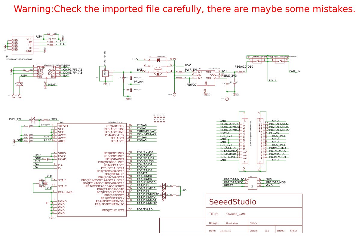
Design Drawing
schematic diagram
(
1
/
)
PCB
(
1
/
)
The preview image was not generated, please save it again in the
editor.
| ID | Name | Designator | Quantity |
|---|---|---|---|
| 1 | 1uF | C4,C1,C5,C3 | 4 |
| 2 | 22R | R1,R3 | 2 |
| 3 | 10k | R14,R6,R5,R9 | 4 |
| 4 | 100nF | C10,C12,C15,C16,C2 | 5 |
| 5 | BLUE | RX,P1 | 2 |
| 6 | 1k | R4,R2 | 2 |
| 7 | 341023001 JST-SMD-2P-1.0-90D | BAT | 1 |
| 8 | 132004001 CN3065-DFN8 | U1 | 1 |
| 9 | 12p FPC bottom contact349067001 | J2,J3 | 2 |
| 10 | 470k_1% | R7,R8 | 2 |
| 11 | 10pF | C6 | 1 |
| 12 | SEEEDSTUDIO_SCH_FRAME | U$1 | 1 |
| 13 | 16MHz | X1 | 1 |
| 14 | DNP | ISP | 1 |
| 15 | ATMEGA32U4 | U2 | 1 |
| 16 | DNP | BATTERY,GND0,GND1,EX5VIN | 4 |
| 17 | DNP | D1 | 1 |
| 18 | 1N4448WT | D2 | 1 |
| 19 | FDFMA2P853 | U3 | 1 |
| 20 | 1M | R10,R11 | 2 |
| 21 | ST-USB-001G340005001 | J4 | 1 |
| 22 | BUTTON-2P-REINFORCE | WAKE,RST | 2 |
| 23 | XC6415GG17ER | U5 | 1 |
| 24 | PAD-MARK | P2,P3,P4,P5,P6,P7,P8,P9 | 8 |
Unfold
Project Members


 0
0
 0
0
Collect to album
Target complaint
Related Projects
Change a batch
Loading...
Add to album
×
Loading...
reminder
×
Do you need to add this project to the album?