


© 2024 EasyEDA Some rights reserved ISO/IEC
Editor Version
×
Standard

1.Easy to use and quick to get started
2.The process supports design scales of 300 devices or 1000 pads
3.Supports simple circuit simulation
4.For students, teachers, creators
Profession

1.Brand new interactions and interfaces
2.Smooth support for design sizes of over 5,000 devices or 10,000 pads
3.More rigorous design constraints, more standardized processes
4.For enterprises, more professional users

Ongoing
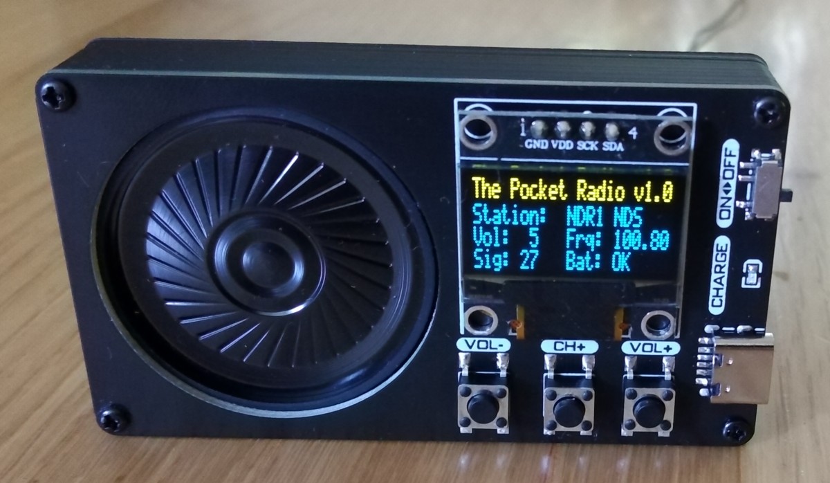
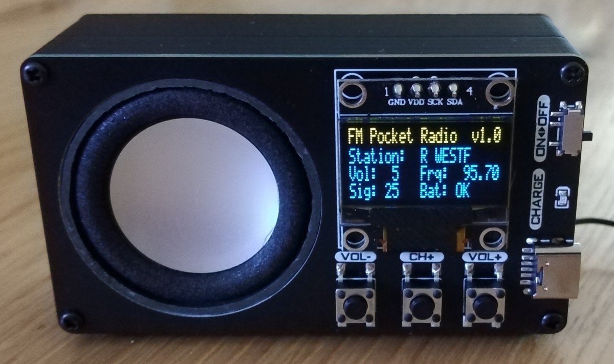
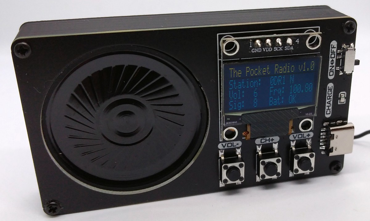
STD ATtiny412 Pocket Radio
License: CC-BY-SA 3.0
Mode: Editors' pick
- 15
Update time:
2022-09-04 17:00:34
Creation time:
2022-06-17 15:30:27
Description
# Overview
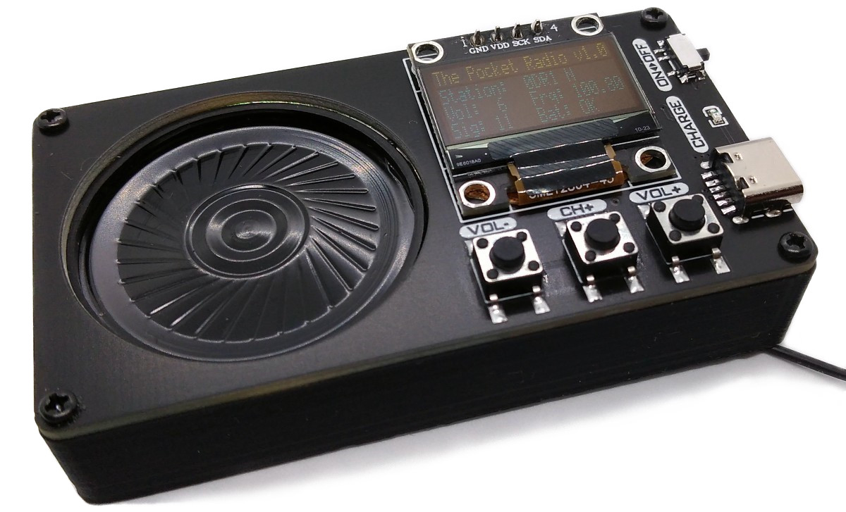
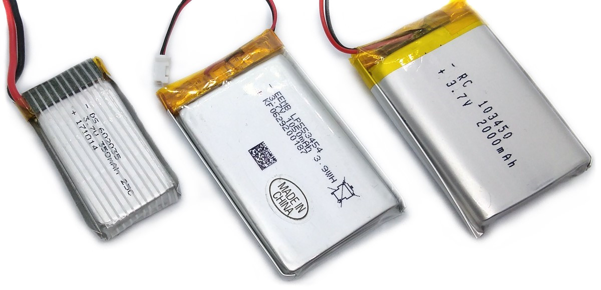
PocketRadio is an ATtiny402/412 controlled FM radio with RDS (RDA5807MP), an integrated audio amplifier (TC8871 or XPT8871), a LiPo battery charger (MCP73831 or TP4054), an OLED display (SSD1306) and three buttons. You can directly connect a protected 3.7V LiPo battery, a 3W / 4Ω speaker and an FM antenna.
* Project Video (YouTube): [https://youtu.be/-taygMlm8Ls](https://youtu.be/-taygMlm8Ls)
* Firmware (Github): https://github.com/wagiminator/ATtiny412-PocketRadio
* Review on Megazoid's Hut (YouTube): https://youtu.be/HVwsa0pgvS4
# Hardware
## Schematic
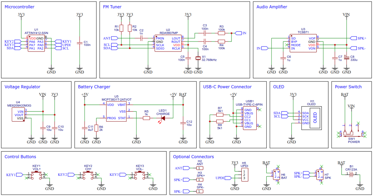
## RDA5807MP FM Radio Tuner IC
The low-cost RDA5807MP is a single-chip broadcast FM stereo radio tuner with fully integrated synthesizer, IF selectivity, RDS/RBDS and MPX decoder. The tuner uses the CMOS process, support multi-interface and require the least external component. All these make it very suitable for portable devices. The RDA5807MP is controlled by the ATtiny via I²C.
## TC8871 Audio Amplifier IC
The TC8871 is an FM-free, Class AB/Class D selectable power amplifier. When the working voltage is 5V, the maximum driving power is 5W (2Ω, BTL load, THD>10%). The application circuit of TC8871 is simple, only a few peripheral devices are needed, and the feedback resistor is integrated; the output does not need an external coupling capacitor or a power-up capacity and buffer network.
The amplification can be selected via the value of the resistors R3 and R4 (Gain = 2 * 100kΩ / (10kΩ + R3), R4 respectively), which determines the maximum volume. Keep in mind that the resistors together with the coupling capacitors C3 and C4 form a high-pass filter whose cut-off frequency is determined using the following formula: f = 1 / (2 * π * R3 * C3), R4 and C4 respectively.
## MCP73831 Li-Ion Battery Charger IC
For battery charging the MCP73831 is used. The MCP73831 is a highly advanced linear charge management controller for use in space-limited, cost-sensitive applications. It employs a constant-current/constant-voltage charge algorithm with selectable preconditioning and charge termination. The constant current value is set with one external resistor (I = 1000V / R6). Charging is done via the built-in USB-C connector. The MCP73831 can be replaced by the much cheaper TP4054.
## ME6209 Voltage Regulator
The ME6209A33 is a 3.3V positive voltage output, three–pin regulator, that provides a high current (up to 250mA) even when the input/output voltage differential is small. Low power consumption (3µA) and high accuracy (+/-2%) is achieved through CMOS technology. It allows input voltages as high as 18V with a dropout voltage around 80mV@40mA.
# Software
## Controlling the RDA5807
The FM tuner IC RDA5807MP is controlled via I²C by the ATtiny. It has six writable 16-bit registers (addresses 0x02 - 0x07) and six readable 16-bit registers (addresses 0x0A - 0x0F). The RDA5807 has two methods of write access, a sequential one in which the registers are always written starting from address 0x02 and an indexed method in which the register address is transferred first and then the content. Both methods are determined by different I²C addresses. To transfer the 16-bit register content, the high byte is sent first. The RDA5807 is controlled by setting or clearing certain bits in the respective registers. The details of the meanings of the individual registers can be found in the data sheet. The current register contents are saved in the RDA_regs arrays. The RDA implementation is based on the work of [Maarten Janssen](https://hackaday.io/project/9009-arduino-radio-with-rds).
## Compiling and Uploading the Firmware
* Connect your [UPDI programmer](https://github.com/wagiminator/AVR-Programmer) to your PC and to the UPDI header on the board. Set your programmer to work at 3.3V!
* Use one of the following methods to compile and upload the firmware:
### If using the Arduino IDE
* Open your Arduino IDE.
* Make sure you have installed [megaTinyCore](https://github.com/SpenceKonde/megaTinyCore).
* Go to **Tools -> Board -> megaTinyCore** and select **ATtiny412/402/212/202**.
* Go to **Tools** and choose the following board options:
* **Chip:** ATtiny402 or 412
* **Clock:** 1 MHz internal
* Leave the rest at the default settings.
* Go to **Tools -> Programmer** and select your UPDI programmer.
* Go to **Tools -> Burn Bootloader** to burn the fuses.
* Open the sketch and click **Upload**.
### If using the makefile (Linux/Mac)
* Download [AVR 8-bit Toolchain](https://www.microchip.com/mplab/avr-support/avr-and-arm-toolchains-c-compilers) and extract the sub-folders (avr, bin, include, ...) to /software/tools/avr-gcc. To do this, you have to register for free with Microchip on the download site.
* Open a terminal.
* Navigate to the folder with the makefile and the sketch.
* Run `DEVICE=attiny412 PROGRMR=serialupdi PORT=/dev/ttyUSB0 make install` to compile, burn the fuses and upload the firmware (change DEVICE, PROGRMR and PORT accordingly).
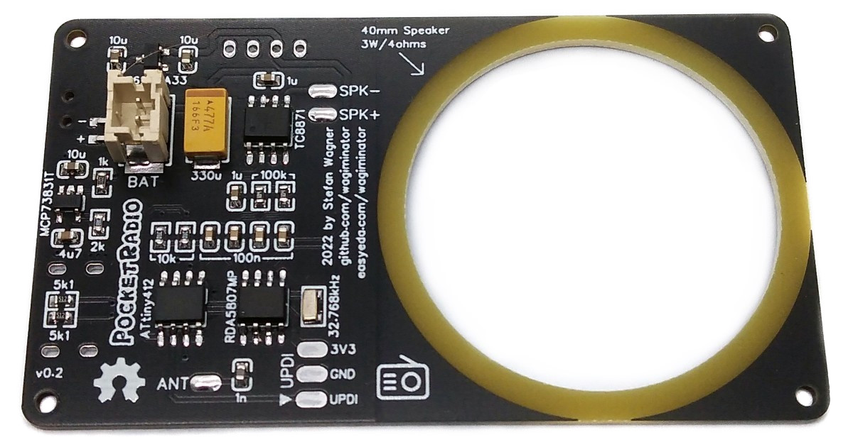
# Building Instructions
Solder all components to the PCB. Place the 40mm speaker in the corresponding cutout on the board. Glue the speaker in place with hot glue. Make sure that the glue is airtight all around to achieve good sound quality. Solder the connection cables between speaker and board. Solder the wire antenna to the corresponding pad on the board. A 75cm (30" = λ / 4) long 28AWG flexible silicone insulated wire works very well.
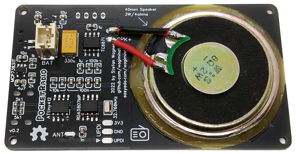
3D print the case. Cases with different heights are available in the "3dprint" folder. Choose the case that matches the height of your battery and speaker. Glue the battery into the case with double-sided tape. Thread the wire antenna through the small hole in the housing. To improve the sound quality, you can pack a foam mat between the battery and the PCB inside the case. This should fit snugly against the outer walls of the housing.
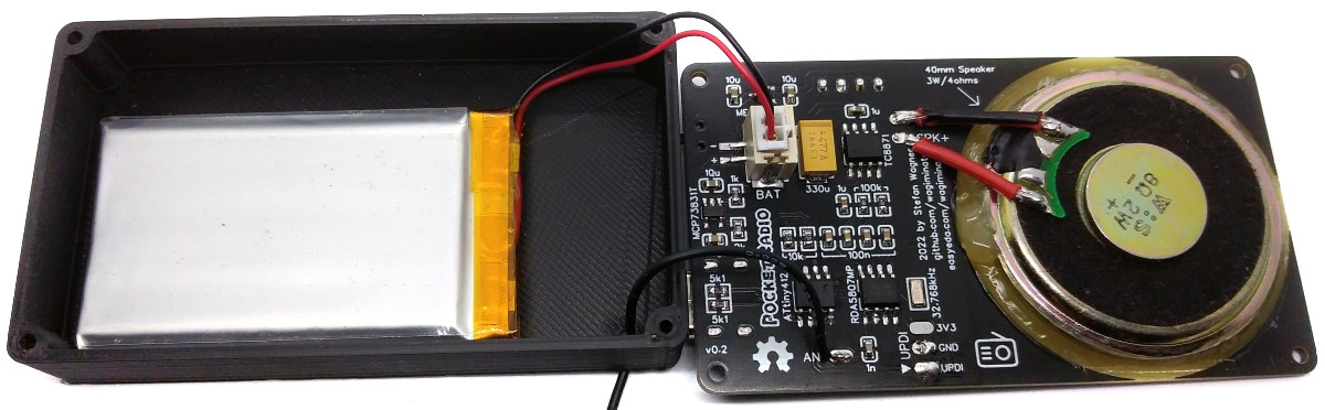
Connect the battery to the JST connector on the board. Pay attention to the correct polarity, unfortunately there is no standard here! At the latest now you should upload the firmware (see above). Use the UPDI pads on the board for this. Place the board on the case and screw it with four M2x5mm self-tapping screws.
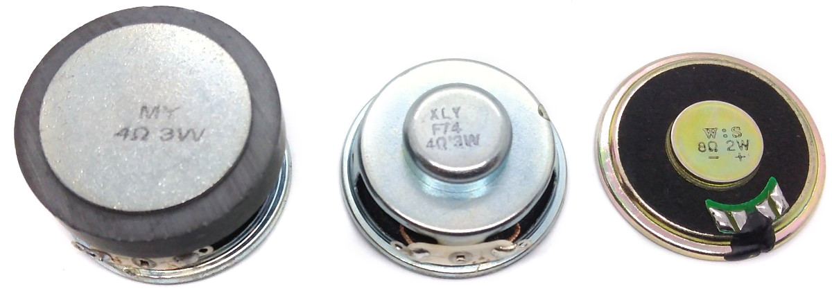
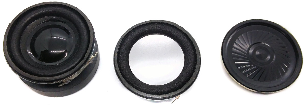
There are different loudspeakers with 40mm diameter. The flatter ones allow the radio to be built more compactly, while the taller ones have better sound quality.
The size of the battery also affects the size of the radio. In operation, the radio consumes around 100mA - 125mA at 3.7V and medium volume. So a battery with a capacity of 1200mAh should provide around 10 hours of playtime.
# Operating Instructions
1. Make sure that the wire antenna is laid as straight as possible horizontally or vertically.
2. Turn on the radio using the power switch.
3. The radio should automatically tune to the last station scanned and volume used.
4. Use the volume buttons to select the volume from 0 to 15.
5. The next station is searched for with the "CH+" button.
6. When the OLED shows "Bat: weak", you should soon recharge the battery via the USB-C port.
# References, Links and Notes
1. [ATtiny412 Datasheet](https://ww1.microchip.com/downloads/aemDocuments/documents/MCU08/ProductDocuments/DataSheets/ATtiny212-214-412-414-416-DataSheet-DS40002287A.pdf)
2. [RDA5807MP Datasheet](https://datasheet.lcsc.com/lcsc/1806121226_RDA-Microelectronics-RDA5807MP_C167245.pdf)
3. [TC8871 Datasheet](https://datasheet.lcsc.com/lcsc/2202252130_Shenzhen-Fuman-Elec-TC8871_C89482.pdf)
4. [MCP73831 Datasheet](https://datasheet.lcsc.com/lcsc/1809191822_Microchip-Tech-MCP73831T-2ATI-OT_C14879.pdf)
5. [ME6209 Datasheet](https://datasheet.lcsc.com/lcsc/1811081822_MICRONE-Nanjing-Micro-One-Elec-ME6209A33M3G_C83508.pdf)
6. [SSD1306 Datasheet](https://cdn-shop.adafruit.com/datasheets/SSD1306.pdf)
7. [ATtiny13A TinyPocketRadio](https://github.com/wagiminator/ATtiny13-TinyPocketRadio)
8. [ATtiny85 TinyFMRadio](https://github.com/wagiminator/ATtiny85-TinyFMRadio)
# License

This work is licensed under Creative Commons Attribution-ShareAlike 3.0 Unported License.
(http://creativecommons.org/licenses/by-sa/3.0/)
Design Drawing
schematic diagram
(
1
/
)
PCB
(
1
/
)
The preview image was not generated, please save it again in the
editor.
| ID | Name | Designator | Footprint | Quantity |
|---|---|---|---|---|
| 1 | CR123A | B1 | TH_L43.0-W-18.0-CR123A | 1 |
| 2 | 100n | C1,C3,C4,C5 | C_0603 | 4 |
| 3 | 1n | C2 | C_0603 | 1 |
| 4 | 1u | C6,C7 | C_0603 | 2 |
| 5 | 330u | C8 | TANTALUM_CASE-D | 1 |
| 6 | 10u | C9,C10,C12 | C_0603 | 3 |
| 7 | 4u7 | C11 | C_0603 | 1 |
| 8 | OLED | H1 | I2C OLED 0.96 NEW | 1 |
| 9 | ANT | H2 | PAD_1 | 1 |
| 10 | SPK+ | H3 | PAD_1 | 1 |
| 11 | SPK- | H4 | PAD_1 | 1 |
| 12 | UPDI | H5 | PAD_3 | 1 |
| 13 | BAT | H6 | CONN-SMD_2P_PH2.0_LT | 1 |
| 14 | SPK | H7 | CONN-SMD_2P_PH2.0_LT | 1 |
| 15 | VOL+ | KEY1 | KEY-6.0*6.0 | 1 |
| 16 | CH+ | KEY2 | KEY-6.0*6.0 | 1 |
| 17 | VOL- | KEY3 | KEY-6.0*6.0 | 1 |
| 18 | CHARGE | LED1 | LED_0603 | 1 |
| 19 | 10k | R1,R2 | 0603 | 2 |
| 20 | 100k | R3,R4 | 0603 | 2 |
| 21 | 1k | R5 | 0603 | 1 |
| 22 | 2k | R6 | 0603 | 1 |
| 23 | 5k1 | R7,R8 | 0603 | 2 |
| 24 | POWER | SW1 | SW-SMD_SS-1290L-GLL-1.5MM | 1 |
| 25 | ATTINY412-SSN | U1 | SOP-8_150MIL | 1 |
| 26 | RDA5807MP | U2 | SOP-8_150MIL | 1 |
| 27 | TC8871 | U3 | SOP-8_EP_150MIL | 1 |
| 28 | ME6209A33M3G | U4 | SOT-23-3_W | 1 |
| 29 | MCP73831T-2ATI/OT | U5 | SOT-23-5_BR | 1 |
| 30 | USB-TYPE-C-6PIN | USB1 | USB-C-SMD-6P | 1 |
| 31 | 32.768kHz | X1 | OSC-SMD_3215 | 1 |
Unfold
Project Members


 17
17
 15
15
Collect to album
Target complaint
Related Projects
Change a batch
Loading...
Add to album
×
Loading...
reminder
×
Do you need to add this project to the album?