


© 2024 EasyEDA Some rights reserved ISO/IEC
Editor Version
×
Standard

1.Easy to use and quick to get started
2.The process supports design scales of 300 devices or 1000 pads
3.Supports simple circuit simulation
4.For students, teachers, creators
Profession

1.Brand new interactions and interfaces
2.Smooth support for design sizes of over 5,000 devices or 10,000 pads
3.More rigorous design constraints, more standardized processes
4.For enterprises, more professional users

Ongoing
STD ATtiny85 TinyFMradio SMD
License: CC-BY-SA 3.0
Mode: Editors' pick
- 37
Update time:
2023-06-05 08:34:05
Creation time:
2019-05-04 10:47:27
Description
# Overview
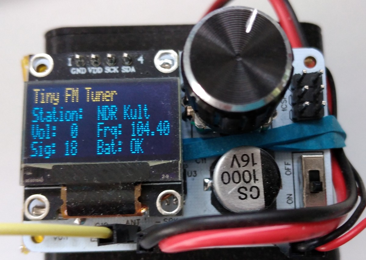
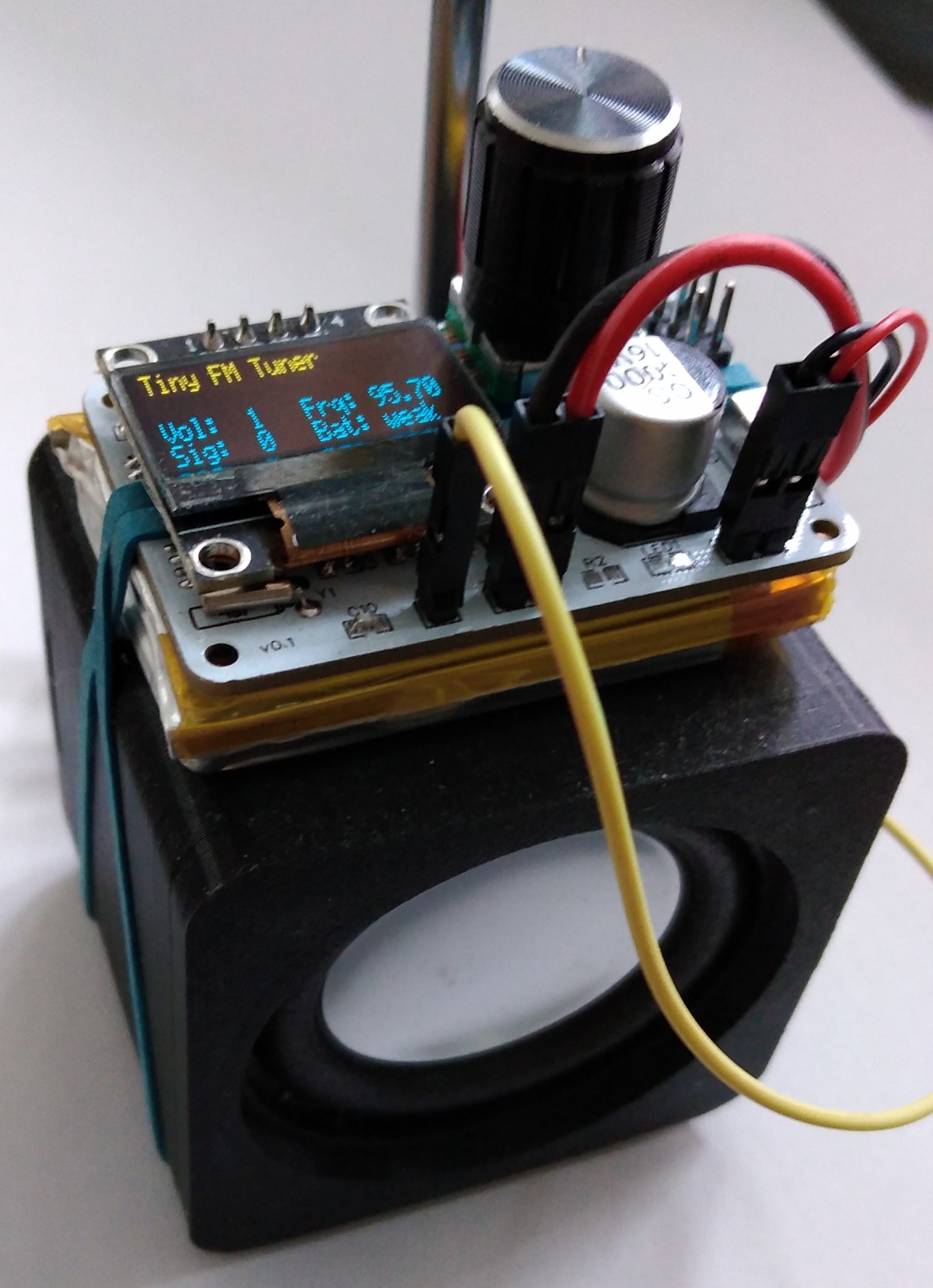
TinyFMRadio is an ATtiny45/85 controlled FM radio with RDS (RDA5807) with an integrated audio amplifier (XPT8871 or TC8871), an OLED display (SSD1306) and a rotary encoder. You can directly connect a protected li-ion battery, a 3W / 4Ω speaker and an FM antenna.
- Project Video (YouTube): https://youtu.be/dG5VVQmySEc
- Firmware (Github): https://github.com/wagiminator/ATtiny85-TinyFMRadio
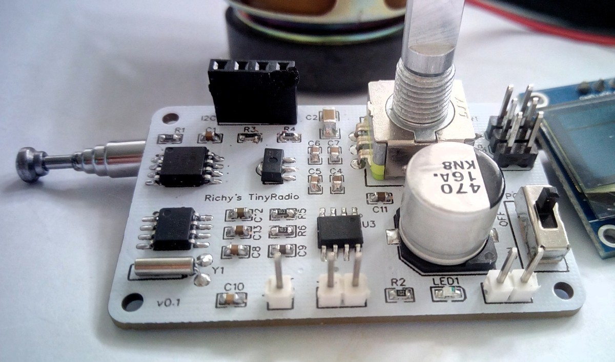
# Hardware
The low-cost RDA5807MP is a single-chip broadcast FM stereo radio tuner with fully integrated synthesizer, IF selectivity, RDS/RBDS and MPX decoder. The tuner uses the CMOS process, support multi-interface and require the least external component. All these make it very suitable for portable devices.
# Software
The firmware is just a demo sketch that implements basic functionality. By pressing the rotary encoder button the RDA5807 seeks the next radio station. Turning the rotary encoder increases/decreases the volume. Selected frequency and volume are stored in the EEPROM. Station name, frequency, signal strength, volume and battery state of charge are shown on an OLED display.
## I²C Implementation
The I²C protocol implementation is based on a crude bitbanging method. It was specifically designed for the limited resources of ATtiny10 and ATtiny13, but should work with some other AVRs as well. Due to the low clock frequency of the CPU, it does not require any delays for correct timing. In order to save resources, only the basic functionalities which are needed for this application are implemented. For a detailed information on the working principle of the I²C implementation visit [TinyOLEDdemo](https://github.com/wagiminator/attiny13-tinyoleddemo).
## Controlling the RDA5807
The FM tuner IC RDA5807MP is controlled via I²C by the ATtiny. It has six writable 16-bit registers (addresses 0x02 - 0x07) and six readable 16-bit registers (addresses 0x0A - 0x0F). The RDA5807 has two methods of write access, a sequential one in which the registers are always written starting from address 0x02 and an indexed method in which the register address is transferred first and then the content. Both methods are determined by different I²C addresses. To transfer the 16-bit register content, the high byte is sent first. The RDA5807 is controlled by setting or clearing certain bits in the respective registers. The details of the meanings of the individual registers can be found in the data sheet. The current register contents are saved in the RDA_regs arrays. The RDA implementation is based on the work of [Maarten Janssen](https://hackaday.io/project/9009-arduino-radio-with-rds).
## Rotary Encoder Implementation
The implementation for the rotary encoder uses pin change interrupts on only one of the pins and is written in such a way that bouncing is automatically suppressed.
## Compiling and Uploading the Software
### If using the Arduino IDE
- Make sure you have installed [ATtinyCore](https://github.com/SpenceKonde/ATTinyCore).
- Go to **Tools -> Board -> ATtinyCore** and select **ATtiny25/45/85 (No bootloader)**.
- Go to **Tools** and choose the following board options:
- **Chip:** ATtiny45 or ATtiny85
- **Clock:** 1 MHz (internal)
- **B.O.D.:** disabled
- Leave the rest at the default settings
- Connect your programmer to your PC and to the ICSP header of the device.
- Go to **Tools -> Programmer** and select your ISP programmer (e.g. [USBasp](https://aliexpress.com/wholesale?SearchText=usbasp)).
- Go to **Tools -> Burn Bootloader** to burn the fuses.
- Open TinyFMRadio sketch and click **Upload**.
### If using the precompiled hex-file
- Make sure you have installed [avrdude](https://learn.adafruit.com/usbtinyisp/avrdude).
- Connect your programmer to your PC and to the ICSP header of the device.
- Open a terminal.
- Navigate to the folder with the hex-file.
- Execute the following command (if necessary replace "t85" with your chip and "usbasp" with the programmer you use):
```
avrdude -c usbasp -p t85 -U lfuse:w:0x62:m -U hfuse:w:0xd7:m -U efuse:w:0xff:m -U flash:w:tinyfmradio.hex
```
### If using the makefile (Linux/Mac)
- Make sure you have installed [avr-gcc toolchain and avrdude](http://maxembedded.com/2015/06/setting-up-avr-gcc-toolchain-on-linux-and-mac-os-x/).
- Connect your programmer to your PC and to the ICSP header of the device.
- Open the makefile and change the chip if you are not using ATtiny85 and the programmer if you are not using usbasp.
- Open a terminal.
- Navigate to the folder with the makefile and the Arduino sketch.
- Run "make install" to compile, burn the fuses and upload the firmware.
# References, Links and Notes
1. [ATtiny25/45/85 Datasheet](https://ww1.microchip.com/downloads/en/DeviceDoc/Atmel-2586-AVR-8-bit-Microcontroller-ATtiny25-ATtiny45-ATtiny85_Datasheet.pdf)
2. [RDA5807MP Datasheet](https://datasheet.lcsc.com/szlcsc/1806121226_RDA-Microelectronics-RDA5807MP_C167245.pdf)
3. [SSD1306 Datasheet](https://cdn-shop.adafruit.com/datasheets/SSD1306.pdf)
4. [TC8871 Datasheet](https://datasheet.lcsc.com/lcsc/2010160933_Shenzhen-Fuman-Elec-TC8871_C89482.pdf)
5. [ATtiny13 TinyPocketRadio](https://github.com/wagiminator/ATtiny13-TinyPocketRadio)
# License

This work is licensed under Creative Commons Attribution-ShareAlike 3.0 Unported License.
(http://creativecommons.org/licenses/by-sa/3.0/)
Design Drawing
schematic diagram
(
1
/
)
PCB
(
1
/
)
The preview image was not generated, please save it again in the
editor.
| ID | Name | Designator | Footprint | Quantity |
|---|---|---|---|---|
| 1 | Header | VIN,SPK | HDR-1X2/2.54 | 2 |
| 2 | HT7333-A | U4 | SOT-89 | 1 |
| 3 | 32.768 khz | Y1 | XTAL-32KHZ | 1 |
| 4 | I2C | I2C | HDR-4X1/2.54 | 1 |
| 5 | 1000uF | C3 | CAP-SMD_D10.0-L10.3-W10.3-H10.2 | 1 |
| 6 | 1k | R2 | 0603 | 1 |
| 7 | 10k | R7,R1,R8,R9 | 0603 | 4 |
| 8 | 20k | R6,R5 | 0603 | 2 |
| 9 | 4k7 | R3,R4 | 0603 | 2 |
| 10 | ATTINY85-20SU | U1 | SOIC-8_208MIL | 1 |
| 11 | Slide Switch | POWER | SLIDE SWITCH DPDT 1P2T JB | 1 |
| 12 | ICSP-6 | ICSP | ICSP-6 | 1 |
| 13 | Rotary Enc | SW1 | BOURNS_PEC11R-4XXXF-SXXXX | 1 |
| 14 | Header | ANT | HDR-1X1/2.54 | 1 |
| 15 | 10u | C7,C4 | 0603 | 2 |
| 16 | 100n | C1,C8,C15,C14,C5,C16,C6 | 0603 | 7 |
| 17 | 1u | C9,C11 | 0603 | 2 |
| 18 | 1n | C10 | 0603 | 1 |
| 19 | 390n | C12,C13 | 0603 | 2 |
| 20 | 47u | C2 | 1206 | 1 |
| 21 | XPT8871ES | U3 | HSOP-8 | 1 |
| 22 | LED-Blue | LED1 | LED-0603 | 1 |
| 23 | RDA5807MP | U2 | SOP-8_150MIL | 1 |
Unfold
Project Members


 13
13
 37
37
Collect to album
Target complaint
Related Projects
Change a batch
Loading...
Add to album
×
Loading...
reminder
×
Do you need to add this project to the album?