


© 2024 EasyEDA Some rights reserved ISO/IEC
Editor Version
×
Standard

1.Easy to use and quick to get started
2.The process supports design scales of 300 devices or 1000 pads
3.Supports simple circuit simulation
4.For students, teachers, creators
Profession

1.Brand new interactions and interfaces
2.Smooth support for design sizes of over 5,000 devices or 10,000 pads
3.More rigorous design constraints, more standardized processes
4.For enterprises, more professional users
Ongoing
STD C64 TapeBuddy64
License: CC-BY-SA 3.0
Mode: Editors' pick
- 2
Update time:
2022-01-28 18:21:47
Creation time:
2021-12-04 14:42:17
Description
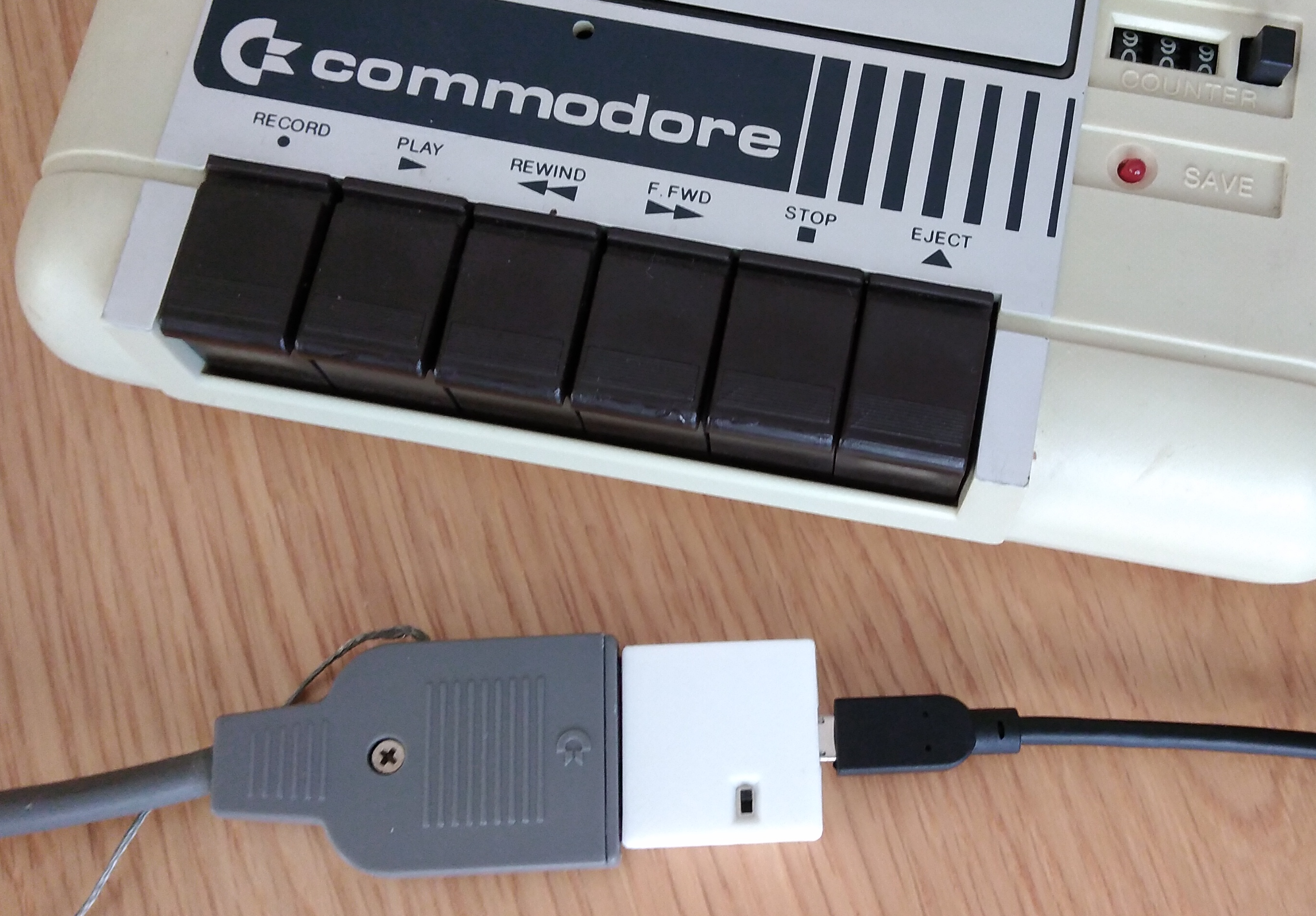
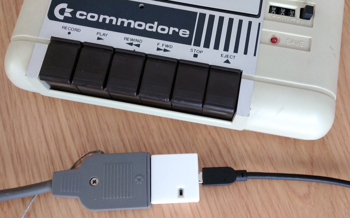
# TapeBuddy64 - Connect your Commodore Datasette to a PC
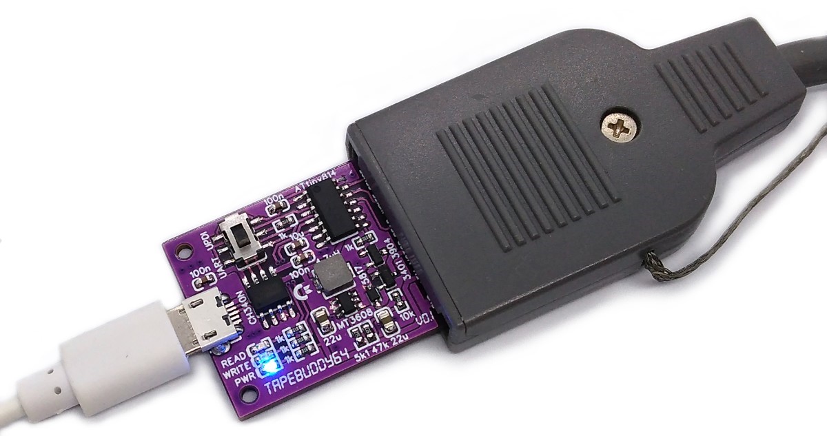
TapeBuddy64 is a simple and inexpensive adapter that can interface a Commodore Datasette to your PC via USB in order to read from and write on tapes. It is an advanced version of the [TapeDump64](https://github.com/wagiminator/C64-Collection/tree/master/C64_TapeDump64). The integrated USB to serial converter can also be used as a SerialUPDI programmer for the on-board ATtiny microcontroller, so that no additional hardware is required to flash the firmware. The TapeBuddy64 is controlled via a command line interface or a graphical front end written in Python.
- Firmware (Github): https://github.com/wagiminator/C64-Collection/tree/master/C64_TapeBuddy64
# Hardware
The schematic is shown below:
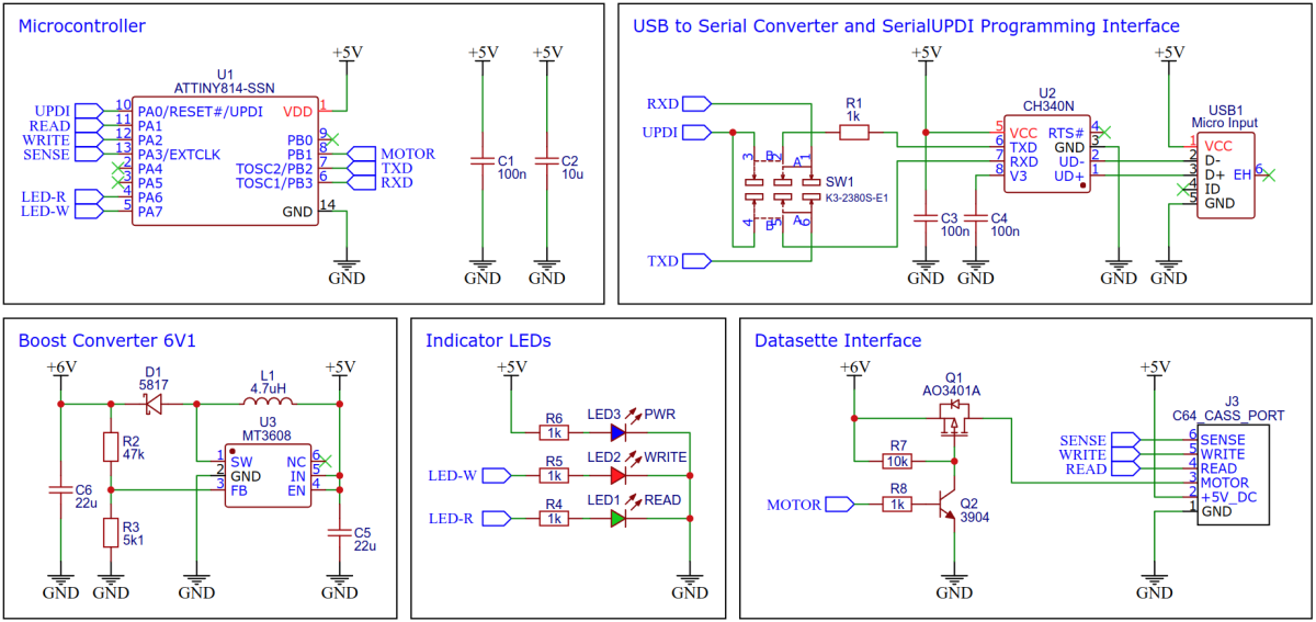
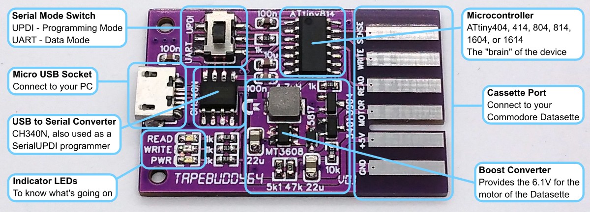
## Microcontroller
I choose one of the (not quite so) new 14-pin [tinyAVRs](https://ww1.microchip.com/downloads/en/DeviceDoc/ATtiny202-204-402-404-406-DataSheet-DS40002318A.pdf) for this project. It has enough pins, hardware UART and a timer/counter B (TCB), which is specially designed for CPU-independent frequency and pulse length measurements. Any of these MCUs can be used: ATtiny404, ATtiny414, ATtiny804, ATtiny814, ATtiny1604, or ATtiny1614. Don't buy them in China, they are much cheaper e.g. at [Digikey](https://www.digikey.de/de/products/detail/microchip-technology/ATTINY404-SSNR/8594960) (€0.56).
## USB to Serial Converter
The [CH340N](https://datasheet.lcsc.com/lcsc/2101130932_WCH-Jiangsu-Qin-Heng-CH340N_C506813.pdf) (or CH330N) is now in use everywhere with me. At around €0.45 (if you buy [10 pieces](https://lcsc.com/product-detail/USB-ICs_WCH-Jiangsu-Qin-Heng-CH340N_C506813.html)) it is very cheap, fast, small, uncomplicated, reliable and hardly requires any external components (not even a crystal). It's probably the best choice for this small project too. And it is also used as a SerialUPDI programmer for the ATtiny.
## Boost Converter
In order to provide the approximately 6.1V for the motor of the Datasette, a boost converter based on the inexpensive [MT3608](https://datasheet.lcsc.com/lcsc/1811151539_XI-AN-Aerosemi-Tech-MT3608_C84817.pdf) is installed on the board. Controlling the motor with 5V would certainly also be possible, but the reduced speed would then have to be compensated by software later. It is difficult to estimate what this would mean for the accuracy of the sampled data. The ATtiny can switch the motor on and off via a MOSFET.
## Cassette Port
The cassette port is a 12-pin edge connector as part of the printed circuit board (PCB) with a spacing of 3.96mm, where 6 pins are on each sides (top and down) of the PCB. The opponent contacts are connected with each other, A with 1, B with 2, and so on. The connector of the datasette is pushed directly onto this port. A notch between B/2 and C/3 prevents accidental polarity reversal.
|Pin|Signal|Description|
|:-|:-|:-|
|A / 1|GND|Ground|
|B / 2|+5V|5 Volt DC|
|C / 3|MOTOR|Motor Control, approx. 6.1 Volt power supply of the motor|
|D / 4|READ|Data Input, read data from Datasette|
|E / 5|WRITE|Data Output, write data to Datasette|
|F / 6|SENSE|Detection, if one of the keys PLAY, RECORD, F.FWD or REW is pressed|
# Software
## Working Principle
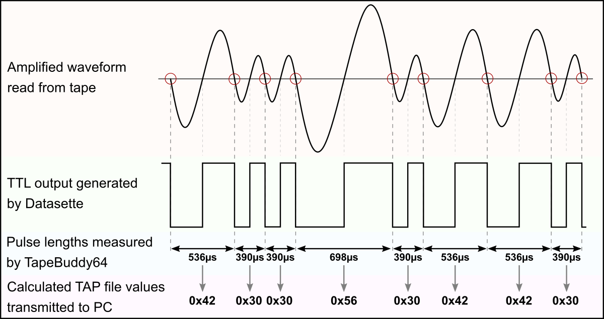
The data is stored on the tape as a frequency modulated waveform. This signal is read from the Datasette, amplified and converted into a TTL-level square wave with the same pulse lengths and then output to the READ pin of the cassette port. TapeBuddy64 reads this square wave and measures the pulse durations between the falling edges of the signal. The associated TAP data bytes are calculated from the pulse lengths, which are then sent to the PC via USB and written there into the TAP file.
Writing on tape works the other way around. TapeBuddy64 generates a square wave with the corresponding pulse lengths according to the TAP data values (the signal is inverted when writing) and sends this via the WRITE pin to the Datasette, which then generates a corresponding waveform and writes it to the cassette.
## Interpretation of the Pulse Lengths
The actual data is coded using a sequence of pulses of different lengths. The standard Commodore system uses patterns of three different pulse lengths: short (390µs), medium (536µs) and long (698µs). Each byte of data is preceded by a marker consisting of a long pulse followed by a medium one. A "0" bit is represented by a short pulse followed by a medium one, while a "1" bit is a medium pulse followed by a short one. Each byte on the tape ends with a parity bit.
However, fast loaders are often used, each of which uses different pulse lengths and patterns, which complicates matters overall. Fortunately, TapeBuddy64 doesn't have to decode the data. This is because only the raw data is saved in the TAP file in the form of the individual pulse lengths. The actual interpretation of these pulses is done later by the C64 or a corresponding emulator.
## Timing Accuracy
The accuracy of the pulse lengths depends on various factors. For example, not all motors in the Datasettes run at exactly the same speed. In addition, the C64 measures the pulse length via the timer of the CIA as the number of passed system clock cycles, but the PAL versions of the C64 have a different clock frequency (985248 Hz) than the NTSC versions (1022730 Hz). Badly aligned heads of the Datasette as well as old tapes with weakened signals contribute to the rest.
That's why the difference between the individual pulse lengths used for the encoding of the data is large enough to be able to reliably differentiate between them even under the circumstances mentioned. In fact, it is not the measured pulse length itself that is relevant, but whether it is above or below a defined threshold value. Furthermore, turbo loaders often use a mechanism to synchronize with the data stream from the datasette.
## TAP File Format
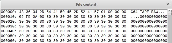
The TAP file format attempts to duplicate the data stored on a C64 cassette tape, bit for bit. It was designed by Per Håkan Sundell (author of the [CCS64](http://www.ccs64.com/) C64 emulator) in 1997. Since it is simply a representation of the raw serial data from a tape, it should handle any custom tape loaders that exist. The layout is fairly simple, with a small 20-byte header followed by the file data:
|Bytes (hex)|Description|
|:-|:-|
|0000-000B|File signature "C64-TAPE-RAW"|
|000C|TAP version (0 - original, 1 - updated, 2 - halfwave extension)|
|000D|Computer platform (0 - C64, 1 - VIC-20, 2 - C16, Plus/4, 3 - PET)|
|000E|Video standard (0 - PAL, 1 - NTSC, 2 - OLD NTSC, 3 - PALN)|
|000F|Future expansion|
|0010-0013|File data size (little endian; not including the header)|
|0014-xxxx|File data|
In TAP version 0, each data byte in the file data area represents the length of a single pulse determined by the following formula:
```data byte = pulse length (in seconds) * C64 clock frequency (in Hertz) / 8```
Therefore, a data value for a pulse length of 390µs would be:
```0.000390s * 985248Hz / 8 = 48 (0x30 in hex)```
A data value of 0x00 represents an "overflow" condition, any pulse length which is more than 255 * 8 clock cycles or 2078µs in length. Such a pulse length does not encode any data and normally only occurs in the pauses between a program and the following one on the same tape. However, the lengths of these pauses can be relevant for some fast loaders.
In TAP version 1, the data value of 0x00 has been re-coded to represent values greater than 255 * 8 clock cycles or values with a greater resolution (one clock cycle instead of eight). When a 0x00 is encountered, three bytes will follow which are the actual pulse length in C64 clock cycles. The three bytes are stored in little endian format (least significant byte first). For example, a data value for a pulse length of 2875µs would look like this:
```0.002875s * 985248Hz = 2832 (data bytes: 0x00, 0x10, 0x0B, 0x00)```
TAP Version 2 is an extension made by Markus Brenner for C16 tapes. It is version 1, but each value represents a halfwave, starting with a '0' to '1' transition. The time encoding doesn't change.
TapeBuddy64 can read TAP versions 0 and 1 and write them to cassette. It uses TAP version 1 to generate a TAP file when reading from the Datasette. The pauses between the individual files on tape are also precisely recorded so that the device should be able to handle all kinds of fast loaders.
## Implementation
### Serial Interface
The Python scripts on the PC control the device via four simple serial commands:
|Command|Function|Response|
|:-:|:-|:-|
|"i"|transmit indentification string|"TapeBuddy64\n"|
|"v"|transmit firmware version number|e.g. "v1.0\n"|
|"r"|read file from tape|send raw data stream|
|"w"|write file on tape|receive raw data stream|
### Reading from Tape
The ATtiny measures the pulse lengths with its timer/counter B (TCB) in frequency measurement mode. The TCB continuously counts upwards at 250kHz until a falling edge is detected at the READ output of the Datasette. The current 16-bit value of the counter is automatically saved, the counter is then reset to zero and restarted. In addition, an interrupt is triggered, in whose service routine the stored value is read out, divided by 2 and pushed into the output buffer for transmission to the PC.
The raw datastream starts with a 0x00 as soon as PLAY on tape was pressed. Each valid pulse the device reads from the tape will be converted into a single non-zero 16-bit word which represents the pulse length in multiples of 8µs and immediately transmitted via UART least significant byte first (little endian). Pulse lengths of less than 8µs are ignored. Values that would be greater than 0x7FFF are divided into several words, the sum of which in turn represents the correct total value. If STOP on tape was pressed or a timeout waiting for valid pulses occurs, the end of the stream is shown with a 0x0000 word. Afterwards, the 16-bit checksum, which is formed from the addition of all data bytes, is transmitted least significant byte first (little endian). Finally, the tape buffer overflow flag is transmitted as a single byte (0x00 means no overflow occured).
If PLAY was not pressed within the defined period of time at the beginning, a 0x01 is sent instead of a 0x00 and the procedure is ended.
The Python script itself writes the TAP file header, converts the received data words into the corresponding TAP values and writes them to the output file.
### Writing on Tape
The Python script on the PC opens the TAP file and checks it. Then it converts all data from the TAP file into the corresponding 16-bit words for transmission to the TapeBuddy64 and stores them in a temporary file. Afterwards it sends the write command "w" to the TapeBuddy64. After receiving a 0x00 byte from the TapeBuddy64, which indicates that RECORD was pressed, it starts to send the first data packet after it was requested by the TapeBuddy64. The TapeBuddy64 temporarily stores the received data in a buffer. As soon as the buffer drops below a certain level, it requests new data from the PC by sending a byte which indicates the number of bytes requested in the next packet.
The ATtiny uses its timer/counter A (TCA) to output a PWM signal with 50% duty cycle at the WRITE pin of the cassette port. After each period a timer overflow interrupt is triggered, in whose service routine the pulse length of the next period is set according to the respective next TAP value which is pulled from the buffer. This creates a very precise, pulse-length modulated square wave.
If there is no more data in the TAP file, the Python script sends a 0x0000 word to indicate the end of the transfer. TapeBuddy64 then sends back a 0x00 byte as soon as all data in the buffer have been output as pulses. Then the 16-bit checksum, the buffer underrun flag and the current status of the RECORD key are transferred to the PC. The Python script checks these values and reports whether the recording was successful.
## Compiling and Uploading the Firmware
- Set the serial mode switch on the device to "UPDI".
- Connect the device to a USB port of your PC.
- Use one of the following methods:
### If using the graphical front end (recommended)
- Execute the respective Python script on your PC: `python tape-gui.py`.
- Click on Flash firmware.
### If using the command line tool
- Execute the respective Python script on your PC: `python flash-firmware.py`.
### If using the Arduino IDE
- Open your Arduino IDE.
- Make sure you have installed [megaTinyCore](https://github.com/SpenceKonde/megaTinyCore).
- Go to **Tools -> Board -> megaTinyCore** and select **ATtiny1614/1604/814/804/414/404/214/204**.
- Go to **Tools** and choose the following board options:
- **Chip:** Select the chip you have installed on your device
- **Clock:** 16 MHz internal
- **Programmer:** SerialUPDI
- Leave the rest at the default settings.
- Go to **Tools -> Burn Bootloader** to burn the fuses.
- Open the TapeBuddy64 sketch and click **Upload**.
### If using the makefile (Linux/Mac)
- Download [AVR 8-bit Toolchain](https://www.microchip.com/mplab/avr-support/avr-and-arm-toolchains-c-compilers) and extract the sub-folders (avr, bin, include, ...) to /software/tools/avr-gcc. To do this, you have to register for free with Microchip on the download site.
- Open a terminal.
- Navigate to the folder with the makefile and the Arduino sketch.
- Run `DEVICE=attiny404 make install` to compile, burn the fuses and upload the firmware (change DEVICE accordingly).
## Installing Python and Drivers
Python needs to be installed on your PC in order to use the software. Most Linux distributions already include this. Windows users can follow these [instructions](https://www.pythontutorial.net/getting-started/install-python/). In addition PySerial and Tkinter (8.6 or newer) must be installed. However, these are already included in most Python installations.
Windows users may also need to install a [driver](http://www.wch.cn/download/CH341SER_ZIP.html) for the CH340N USB to serial adapter. This is not necessary for linux users.
# Operating Instructions
## Preparation
- Set the serial mode switch on your TapeBuddy64 to "UART"
- Connect your TapeBuddy64 to your Commodore Datasette
- Connect your TapeBuddy64 to a USB port of your PC
## Command Line Interface
The following command line tools are available:
### Reading from Tape
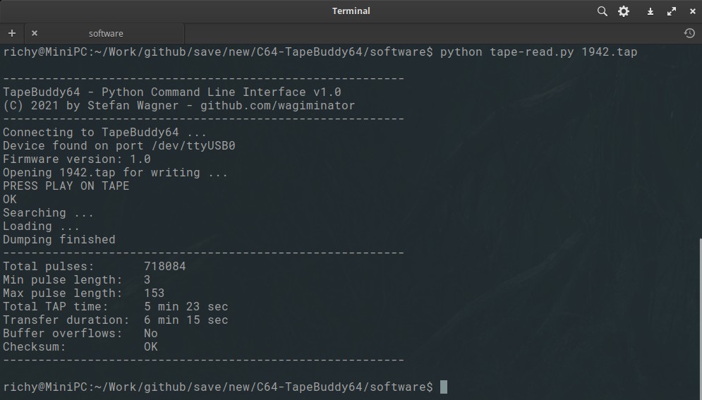
- Execute the respective Python script on your PC: `python tape-read.py outputfile.tap`.
- Press PLAY on your Datasette when prompted.
- The dumping is done fully automatically. It stops when the end of the cassette is reached, when there are no more signals on the tape for a certain time, or when the STOP button on the Datasette is pressed.
### Writing on Tape
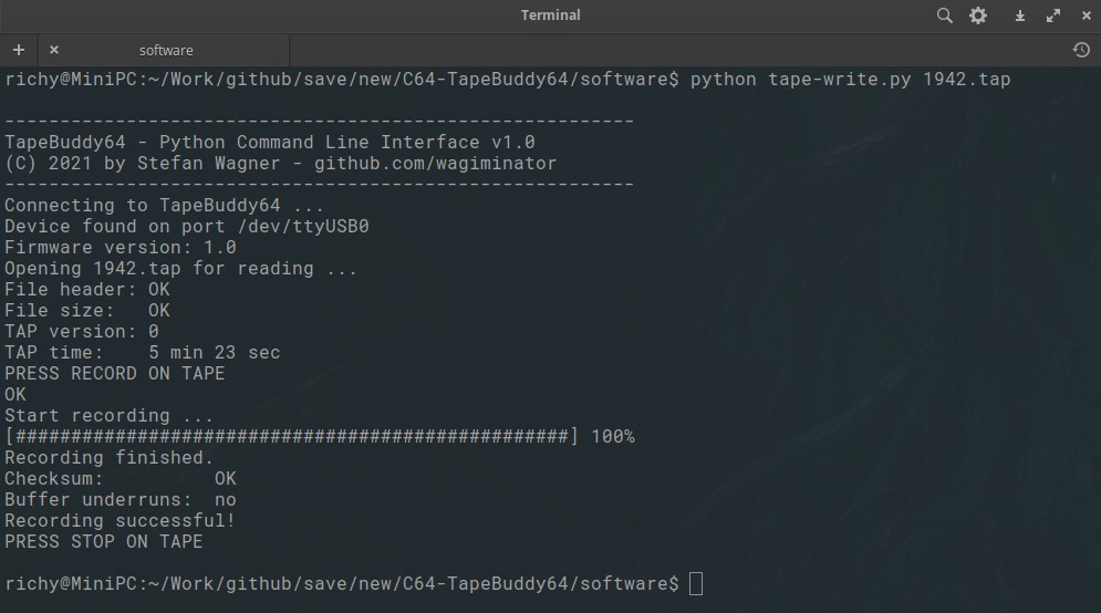
- Execute the respective Python script on your PC: `python tape-write.py inputfile.tap`.
- Press RECORD on your Datasette when prompted.
- The recording is done fully automatically. It stops when all data is written, the end of the cassette is reached, or when the STOP button on the Datasette is pressed.
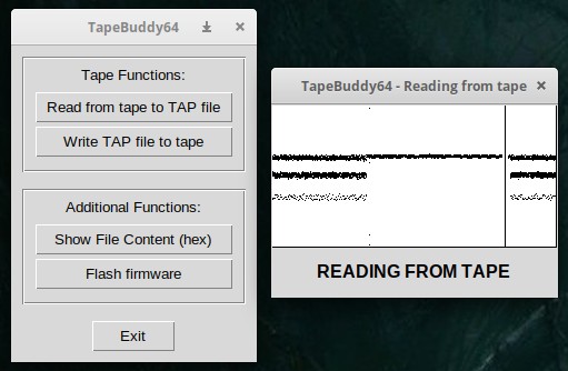
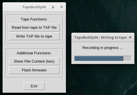
## Graphical User Interface
- Execute the respective Python script on your PC: `python tape-gui.py`.
- The rest should be self explanatory.
## Status LEDs
|LED|Description|
|:-|:-|
|PWR|Steady: device is powered via USB|
|READ|Steady: device is reading from tape
Flashing: device waits for PLAY or STOP being pressed| |WRITE|Steady: device is writing on tape
Flashing: device waits for RECORD or STOP being pressed| ## Checking, Cleaning and Converting TAP Files The TAP files generated by TapeBuddy64 can be used directly in your favorite emulator or with the [Tapuino](https://github.com/wagiminator/C64-Collection/tree/master/C64_Tapuino), but perhaps you want to check it beforehand, optimize it or convert it into another format. This works perfectly with the command line tool [TAPClean](https://sourceforge.net/projects/tapclean/). To check the quality of the generated TAP image, use the following command: `tapclean -t outputfile.tap` Remember, a TAP file is almost never 100% clean, as pauses in particular are not always correctly recognized. You can optimize the quality of the file with the following command: `tapclean -o outputfile.tap` Slight deviations in the pulse lengths are compensated for and everything is adapted to the exact timing specifications. TAPClean not only knows the required pulse lengths of the standard Commodore coding, but also those of all common fast loaders. If you want to convert the TAP file into a WAV audio file, then use the following command: `tapclean -wav outputfile.tap` There is also a graphical [front end](https://www.luigidifraia.com/software/) for TAPClean. ## Datasette Head Alignment If you have problems loading programs from tape, the azimuth of the tape head may be out of position. Before setting the azimuth, however, all other causes of error should be ruled out. Try other cassettes first, as the tapes will age over time and the signals will weaken. Also clean the connector contacts with contact cleaner and the read head with isopropyl alcohol. If it still doesn't work, it's time for the screwdriver. To make the azimuth setting, there is a tiny screw hole above the rewind button through which a small jeweler's screwdriver can fit. When the tape drive is playing, the hole will align with the head adjustment screw. Don't put too much pressure on and avoid over-tightening or over-loosening the screw! Follow these steps: - Insert a cassette into the Datasette that you know is working well. - Execute `python tape-gui.py` - Select "Read from tape to TAP file", then select the output file. You can delete it later. - Press PLAY on the Datasette when prompted. - As soon as the pulse lines are displayed, take a thin screwdriver and slowly adjust the azimuth until the displayed lines are as narrow as possible. 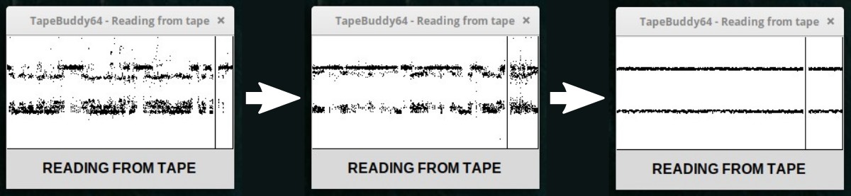 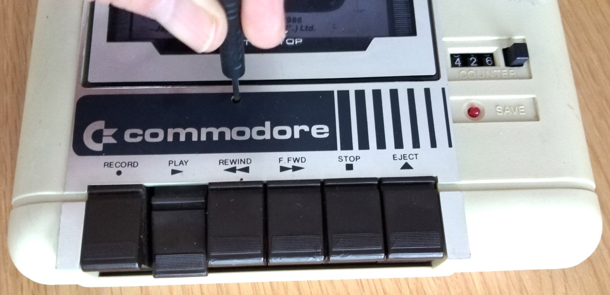 # References, Links and Notes 1. [TapeDump64 Project](https://github.com/wagiminator/C64-Collection/tree/master/C64_TapeDump64) 2. [TrueTape64 Project](https://github.com/francescovannini/truetape64) 3. [Tapuino Project](https://github.com/wagiminator/C64-Collection/tree/master/C64_Tapuino) 4. [How Commodore Tapes Work](https://wav-prg.sourceforge.io/tape.html) 5. [How TurboTape Works](https://www.atarimagazines.com/compute/issue57/turbotape.html) 6. [Analyzing C64 Tape Loaders](https://github.com/binaryfields/zinc64/blob/master/doc/Analyzing%20C64%20tape%20loaders.txt) 7. [Archiving C64 Tapes Correctly](https://www.pagetable.com/?p=1002) 8. [TAP File Format](https://ist.uwaterloo.ca/~schepers/formats/TAP.TXT) 9. [VICE Emulator File Formats](https://vice-emu.sourceforge.io/vice_17.html) 10. [TAPClean](https://sourceforge.net/projects/tapclean/) 11. [TAPClean Front End](https://www.luigidifraia.com/software/) 12. [Datasette Service Manual](https://www.vic-20.it/wp-content/uploads/C2N-1530-1531_service_manual.pdf) 13. [Adjusting the Datassette Head Azimuth](https://theokoulis.com/index.php/2020/11/15/some-notes-on-adjusting-the-datassette-head-azimuth-on-the-vic-20/) 14. [ATtiny Datasheet](https://ww1.microchip.com/downloads/en/DeviceDoc/ATtiny202-204-402-404-406-DataSheet-DS40002318A.pdf) 15. [CH340N Datasheet](https://datasheet.lcsc.com/lcsc/2101130932_WCH-Jiangsu-Qin-Heng-CH340N_C506813.pdf) 16. [MT3608 Datasheet](https://datasheet.lcsc.com/lcsc/1811151539_XI-AN-Aerosemi-Tech-MT3608_C84817.pdf) 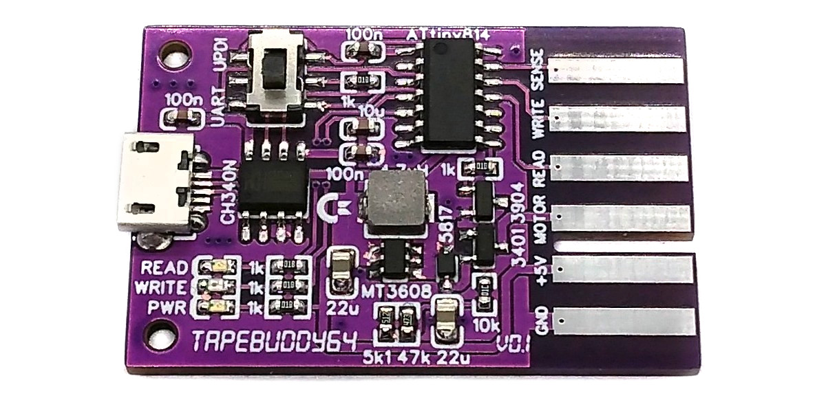    # License  This work is licensed under Creative Commons Attribution-ShareAlike 3.0 Unported License. (http://creativecommons.org/licenses/by-sa/3.0/)
Design Drawing
schematic diagram
(
1
/
)
PCB
(
1
/
)
The preview image was not generated, please save it again in the
editor.
BOM
Project Members


 3
3
 2
2
Collect to album
Target complaint
Related Projects
Change a batch
Loading...
Add to album
×
Loading...
reminder
×
Do you need to add this project to the album?