


© 2024 EasyEDA Some rights reserved ISO/IEC
Editor Version
×
Standard

1.Easy to use and quick to get started
2.The process supports design scales of 300 devices or 1000 pads
3.Supports simple circuit simulation
4.For students, teachers, creators
Profession

1.Brand new interactions and interfaces
2.Smooth support for design sizes of over 5,000 devices or 10,000 pads
3.More rigorous design constraints, more standardized processes
4.For enterprises, more professional users

Ongoing
STD ATmega TransistorTester SMD
License: CC-BY-SA 3.0
Mode: Editors' pick
- 99
Update time:
2022-05-28 18:50:08
Creation time:
2019-07-06 18:27:46
Description
# Overview
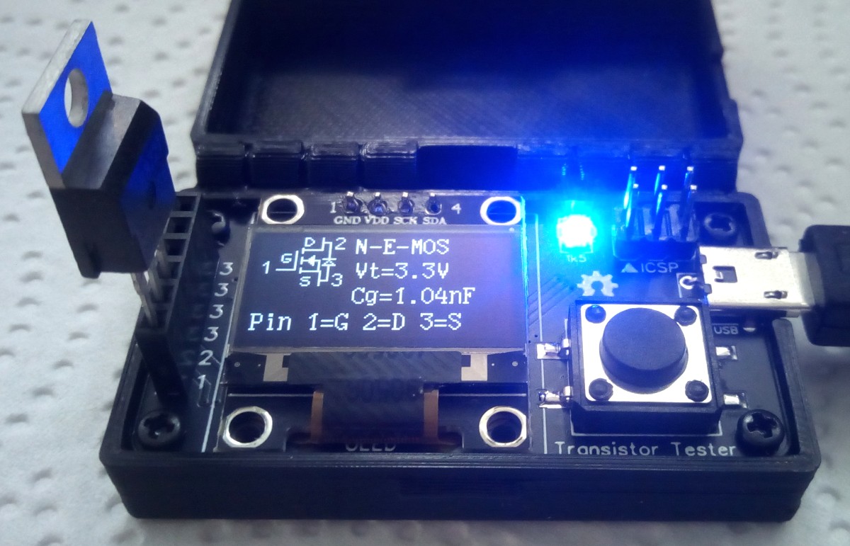
The ATmega328p Transitor Tester is a pocket-sized version of the famous component tester developed by Markus Frejek and Karl-Heinz Kübbeler featuring automatic detection of NPN and PNP bipolar transistors, N- and P-channel MOSFETs, JFETs, diodes, double diodes, N- and P-IGBTs, thyristors, triacs, inductors, resistors and capacitors.
- Project Video (YouTube): https://youtu.be/J4nZ0n5suDk
- Firmware (Github): https://github.com/wagiminator/ATmega-Transistor-Tester
- Original Project: https://www.mikrocontroller.net/articles/AVR_Transistortester
# Compiling and Installing Firmware
You can either compile the firmware yourself (folder: /software/sources), or you can upload the precompiled binary (folder: /software/binaries). Current versions of the firmware can be downloaded from the [Github page](https://github.com/Mikrocontroller-net/transistortester) of the original project.
## Compiling Firmware (Linux/Mac)
- Make sure you have installed [avr-gcc toolchain and avrdude](http://maxembedded.com/2015/06/setting-up-avr-gcc-toolchain-on-linux-and-mac-os-x/).
- Open the makefile in the folder /software/sources/make and change the setting (e.g. language) if you want.
- Open a terminal.
- Navigate to the folder with the makefile.
- Run "make". Among others, the hex and eep files are generated, which can then be uploaded into the ATmega.
## Uploading Firmware
- Make sure you have installed [avrdude](https://learn.adafruit.com/usbtinyisp/avrdude).
- Connect your programmer to your PC and to the ICSP header of the device.
- Open a terminal.
- Navigate to the folder with the hex and eep files.
- Execute the following commands (if necessary replace "usbasp" with the programmer you use):
```
avrdude -c usbasp -p m328p -U lfuse:w:0xff:m -U hfuse:w:0xdb:m -U efuse:w:0xfd:m
avrdude -c usbasp -p m328p -U flash:w:TransistorTester.hex
avrdude -c usbasp -p m328p -U eeprom:w:TransistorTester.eep
```
# Operating Instructions
## Precautions
It should be noted that the test inputs do not have a protective circuit. A protective circuit would probably also falsify the measurement results. Always **discharge the capacitors** before connecting them to the tester! The tester can be damaged before you turn it on. Particular care should be taken when attempting to test components mounted on a circuit. In any case, the device should be disconnected from the power supply and you should be sure that there is **no residual voltage**.
## Testing a Component
1. Connect the Transistor Tester via the Micro-USB port to a 5V power supply.
2. Plug the component to be tested into the socket row. Each pin of the component should have its unique socket number (1 to 3).
3. Press the TEST button and wait for the result shown on the OLED display.
## Characteristics
|Component|Measuring Range|
|-|-|
|Resistors|100mOhm – 50MOhm|
|Capacitors|35pF – 100mF|
|Inductors|0.01mH – 20H|
|Z-Diodes|max 4.5V|
- One-key-operation
- Three test pins for universal use.
- Automated detection of NPN, PNP, N- and P-channel MOSFET, JFET, diodes und small thyristors, TRIAC.
- Automated detection of pin assignment, this means the device-under-test can be connected to the tester in any order.
- Measurement of hFE and base-emitter-voltage for bipolar junction transistors, also for Darlingtons.
- Automated detection of protection diodes in bipolar junction transistors and MOSFETs.
- Bipolar junction transistors are detected as a transistor with a parasitic transistor (NPNp = NPN + parasitic PNP).
- Up to two resistors will be measured with a resolution down to 0.1 Ohm. The measurement range is up to 50 MOhm (Megaohm). Resistors below 10 Ohm will be measured with the ESR approach and a resolution of 0.01 Ohm. Beware: resolution is not accuracy.
- Capacitors in the range 35pF (picofarad) to 100mF (millifarad) can be measured with a resolution down to 1 pF (0.01 pF for capacitors with lower capacity than 100 pF).
- Resistors and capacitors will be displayed with their respective symbol, pin number and value.
- Up to two diodes will also be displayed with their correctly aligned symbol, pin number and voltage drop.
- If it's a single diode, the parasitic capacitance and reverse current will also be measured.
- Inductances of 0.01 mH to 20 H can be detected and measured.
- A measurement of ESR (Equivalent Series Resistance) of capacitors greater than 20 nF is built in. The resolution is 0.01 Ohm. For lower capacity values the accuracy of ESR result becomes worse.
- Vloss of capacitors greater 5 nF is examined. With this it is possible to estimate its Q-factor.
# References, Links and Notes
1. [Original Project Description](https://www.mikrocontroller.net/articles/AVR_Transistortester)
2. [Original Documentation](https://github.com/Mikrocontroller-net/transistortester/raw/master/Doku/trunk/pdftex/english/ttester.pdf)
3. [Original Firmware](https://github.com/Mikrocontroller-net/transistortester)
Design Drawing
schematic diagram
(
1
/
)
PCB
(
1
/
)
The preview image was not generated, please save it again in the
editor.
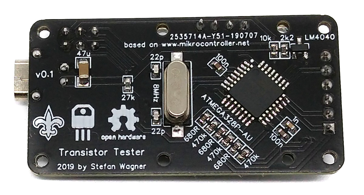
| ID | Name | Designator | Footprint | Quantity |
|---|---|---|---|---|
| 1 | LM4040DYM3-2.5-TR | U2 | SOT-23(SOT-23-3) | 1 |
| 2 | 470k | R7,R9,R5 | 0603 | 3 |
| 3 | 2k2 | R10 | 0603 | 1 |
| 4 | 27k | R3 | 0603 | 1 |
| 5 | 680R | R8,R4,R6 | 0603 | 3 |
| 6 | 10k | R1 | 0603 | 1 |
| 7 | 1k5 | R2 | 0603 | 1 |
| 8 | SMD-Tactile-Switch-12X12X6MM | TEST | SW-SMD_4PIN-L12.0-W12.0-H6.0 | 1 |
| 9 | OLED | OLED | OLED | 1 |
| 10 | USB PWR Connector | USB | USB PWR CONNECTOR | 1 |
| 11 | ICSP-6 | ICSP | ICSP-6-B | 1 |
| 12 | 1n | C3 | 0603 | 1 |
| 13 | 100n | C2,C1 | 0603 | 2 |
| 14 | 22p | C6,C5 | 0603 | 2 |
| 15 | 47u | C4 | 1206 | 1 |
| 16 | PWR | LED1 | LED-0603 | 1 |
| 17 | 8MHz | X1 | HC-49SMD | 1 |
| 18 | Header | TESTPORT | HDR-6X1/2.54 | 1 |
| 19 | ATMEGA328P-AU | U1 | TQFP-32_7X7X08P | 1 |
Unfold
Project Members


 57
57
 99
99
Collect to album
Target complaint
Related Projects
Change a batch
Loading...
Add to album
×
Loading...
reminder
×
Do you need to add this project to the album?