


© 2024 EasyEDA Some rights reserved ISO/IEC
Editor Version
×
Standard

1.Easy to use and quick to get started
2.The process supports design scales of 300 devices or 1000 pads
3.Supports simple circuit simulation
4.For students, teachers, creators
Profession

1.Brand new interactions and interfaces
2.Smooth support for design sizes of over 5,000 devices or 10,000 pads
3.More rigorous design constraints, more standardized processes
4.For enterprises, more professional users

Ongoing
STD ATtiny13 Soldering Station SMD
License: CC-BY-SA 3.0
Mode: Editors' pick
- 41
Update time:
2023-02-20 15:06:04
Creation time:
2020-02-27 18:02:13
Description
# Overview
TinySolder is a simple T12 Quick Heating Soldering Station based on the ATtiny13A featuring in less than 500 bytes of code:
- Temperature measurement of the tip
- Direct control of the heater
- Temperature control via potentiometer
- Handle movement detection (by checking ball switch)
- Time driven sleep/power off mode if iron is unused (movement detection)

- Project Video (YouTube): https://youtu.be/LOpmxG2Fvpo
- Firmware (Github): https://github.com/wagiminator/ATtiny13-TinySolder
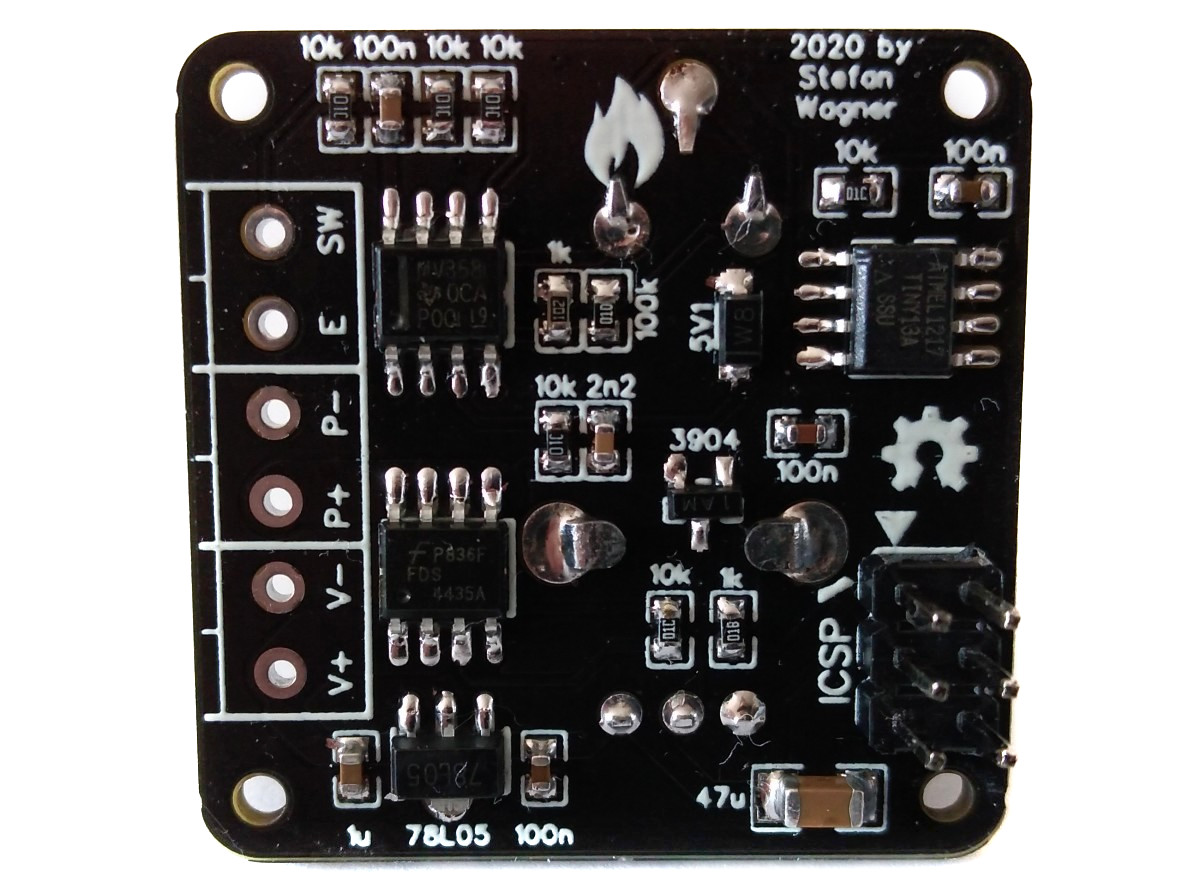
# Hardware
## Heater Control
To switch the heater on and off, it is controlled via an [AO4435](https://datasheet.lcsc.com/szlcsc/Alpha-Omega-Semicon-AOS-AO4435_C79714.pdf) p-channel MOSFET. The MOSFET is designed for voltages up to 30V and currents up to 10A. Its resistance is relatively low at 14 milliohms, which guarantees high efficiency and low heat generation on the MOSFET itself. There are many 4435 MOSFETs available from different manufacturers with slightly different specifications. It should be ensured that a 4435 with a gate-source voltage of +/-25V is selected.
## Temperature Measurement
A thermocouple (temperature sensor) is located inside the T12 soldering tip. It creates a very small voltage depending on the temperature difference between the hot end and the cold junction. To measure this, the heater must be switched off since heater and thermocouple are connected in series. The low voltage is amplified by the OpAmp and measured by the ADC of the microcontroller. The gain factor of the OpAmp is controlled via the calibration potentiometer within fixed limits. The [LMV358](https://datasheet.lcsc.com/szlcsc/Texas-Instruments-TI-LMV358IDR_C63813.pdf) is a very cheap and versatile OpAmp, but not the ideal choice for this task because it has a fairly high input offset voltage and is quite noisy. For this kind of soldering station, however, it delivers completely sufficient values. Should a higher accuracy be required, an [OPA2330AIDR](https://datasheet.lcsc.com/szlcsc/1810181613_Texas-Instruments-OPA2330AIDR_C128746.pdf) or [OPA2333AIDR](https://datasheet.lcsc.com/szlcsc/1809200040_Texas-Instruments-OPA2333AIDR_C38732.pdf) can be used instead of the LMV358. Since these OpAmps have the same pinout, no further changes need to be made.
## Voltage Regulator
Since the ATtiny13A and the OpAmp only consume very little power, a small voltage regulator of the type [78L05](https://datasheet.lcsc.com/szlcsc/1811151533_Guangdong-Hottech-78L05_C181132.pdf) is completely sufficient for obtaining the 5V supply voltage. Because of the low current it has to deliver, it hardly heats up despite the relatively high voltage gradient.
# Software
## Implementation
In order to determine the temperature of the soldering tip, the heater must first be switched off. The output voltage of the OpAmp is then measured using the analog-to-digital converter (ADC) and the temperature is determined from this using a two-step linear approximation. The setting of the temperature selection potentiometer is also determined via the ADC. If the temperature of the soldering tip is below the selected setpoint, the heater is then switched on again via the MOSFET, otherwise it remains off for the time being.
A sleep timer runs all the time, which is reset by a pin change interrupt as soon as the tilt switch in the handle of the soldering iron changes its state. If the handle is not moved for about 5 minutes, the system switches to sleep mode, in which the temperature is reduced to about 125°C. If the handle is not moved for another 5 minutes, the heater will be switched off completely. As soon as the handle is moved, the operating mode is switched back to.
The main loop of the code is shown below:
```c
// Loop
while(1) {
// Read potentiometer setting and calculate setpoint accordingly
poti = ADC_read(pinADC(POTI));
if (poti >9) + TEMP150;
else setpoint = (uint32_t)(((poti - 512) * (TEMP450 - TEMP300))>>9) + TEMP300;
// Set heater according to temperature reading and setpoint
pinLow(HEATER); // shut off heater
_delay_us(TIME2SETTLE); // wait for voltages to settle
temp = ADC_read(pinADC(TEMP)); // read temperature
smooth = ((smooth > 3; // low pass filter
if (smooth setpoint) && (setpoint + 10 > smooth)) pinHigh(LED);
// Some timing
if (handleTimer++ > TIME2SLEEP/CYCLETIME*1000) sleep(); // sleep mode if handle unused
_delay_ms(CYCLETIME - 8); // wait for next cycle
}
```
## Compiling and Uploading
### If using the Arduino IDE
- Make sure you have installed [MicroCore](https://github.com/MCUdude/MicroCore).
- Go to **Tools -> Board -> MicroCore** and select **ATtiny13**.
- Go to **Tools** and choose the following board options:
- **Clock:** 1.2 MHz internal osc.
- **BOD:** BOD 2.7V
- **Timing:** Micros disabled
- Connect your programmer to your PC and to the ICSP header on the TinySolder board.
- Go to **Tools -> Programmer** and select your ISP programmer (e.g. [USBasp](https://aliexpress.com/wholesale?SearchText=usbasp)).
- Go to **Tools -> Burn Bootloader** to burn the fuses.
- Open TinySolder.ino and click **Upload**.
### If using the precompiled hex-file
- Make sure you have installed [avrdude](https://learn.adafruit.com/usbtinyisp/avrdude).
- Connect your programmer to your PC and to the ICSP header on the TinySolder board.
- Open a terminal.
- Navigate to the folder with the hex-file.
- Execute the following command (if necessary replace "usbasp" with the programmer you use):
```
avrdude -c usbasp -p t13 -U lfuse:w:0x2a:m -U hfuse:w:0xfb:m -U flash:w:tinysolder.hex
```
### If using the makefile (Linux/Mac)
- Make sure you have installed [avr-gcc toolchain and avrdude](http://maxembedded.com/2015/06/setting-up-avr-gcc-toolchain-on-linux-and-mac-os-x/).
- Connect your programmer to your PC and to the ICSP header on the TinySolder board.
- Open the makefile and change the programmer if you are not using usbasp.
- Open a terminal.
- Navigate to the folder with the makefile and sketch.
- Run "make install" to compile, burn the fuses and upload the firmware.
# Building Instructions
In addition to the components for the PCB you will need the following:
- 3D-printed case
- GX12 Aviator Plug (4- or 5-pin depending on your iron handle)
- DC Power Jack (5.5 * 2.1 mm)
- Rocker Switch (KCD1 15 * 10 mm)
- Some wires
- 4 Self-tapping screws (2.3 * 5 mm)
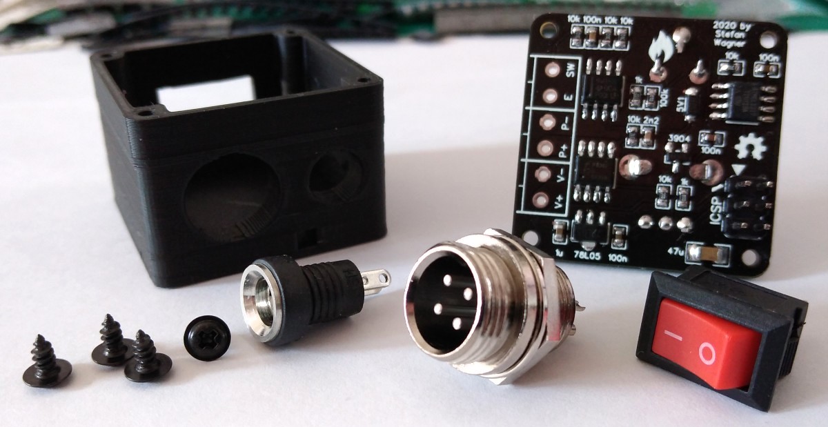
Make sure that all parts fit nicely into the case. Solder the wires to the connectors and protect them with heat shrinks. Use thick wires (AWG18) for the power connections. Make all connections according to the schematic down below but keep in mind, that there's no standard pinout. Solder the wires directly to the corresponding pads on the pcb. To make the soldering station ESD-safe, connect the earth (E) terminal of the aviator plug to a female dupont connector and glue it into the corresponding opening on the case. Now you can connect the soldering station via a male dupont connector to an earth terminal. Upload the firmware and screw the pcb on top of the case.
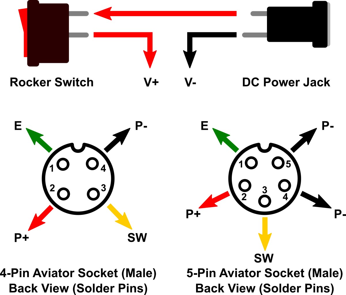
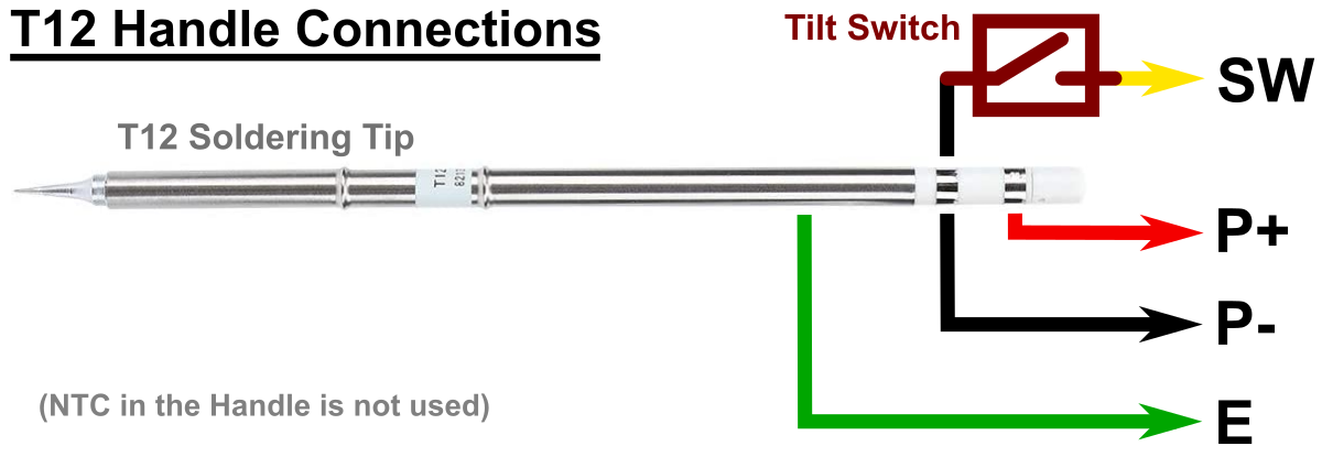
The pinout shown works for the [Quecoo handles from aliexpress](https://aliexpress.com/wholesale?SearchText=quecoo+handle). Different handles may have different pinouts. If you are assembling your handle yourself, follow the scheme shown below. The video by [John Glavinos (electronics4all)](https://www.youtube.com/watch?v=DcmiFfuZw38) shows how it's done.
# Operating Instructions
## Power Supply Specification Requirements
Choose a power supply with an output voltage between 16V and 24V which can provide an output current according to the table below. The power supply must be well stabilized. The current and power is determined by the resistance (R = 8 Ohm) of the heater.
|Voltage (U)|Current (I) = U / R|Power (P) = U² / R|
|:-|:-|:-|
|16 V|2.00 A|32 W|
|17 V|2.13 A|36 W|
|18 V|2.25 A|41 W|
|19 V|2.38 A|45 W|
|20 V|2.50 A|50 W|
|21 V|2.63 A|55 W|
|22 V|2.75 A|61 W|
|23 V|2.88 A|66 W|
|24 V|3.00 A|72 W|
## Calibrating
For calibration you need a [soldering iron tips thermometer](https://aliexpress.com/wholesale?SearchText=digital+soldering+tip+thermometer). For best results wait at least three minutes after switching on the soldering station before you start the calibration. Calibrate at your prefered temperature using the
trimpot.
## Indicator LEDs
|LED|Color|Status|
|:-|:-|:-|
|POWER|blue|lights up when the station is receiving power|
|HEAT|red|tip temperature has not reached setpoint yet|
|WORKY|green|tip temperature is at setpoint - iron is worky|
|HEAT + WORKY|red + green|blinking: iron is in sleep mode; steady: iron is in off mode; move handle to wake up|
# References, Links and Notes
1. [ATtiny13A Datasheet](http://ww1.microchip.com/downloads/en/DeviceDoc/doc8126.pdf)
2. [LMV358 Datasheet](https://datasheet.lcsc.com/szlcsc/Texas-Instruments-TI-LMV358IDR_C63813.pdf)
3. [T12 Handles on Aliexpress](https://aliexpress.com/wholesale?SearchText=T12+GX12-4pin+handle)
4. [T12 Soldering Tips on Aliexpress](https://aliexpress.com/wholesale?SearchText=T12+soldering+tips)
5. [GX12 Aviator Plugs on Aliexpress](https://aliexpress.com/wholesale?SearchText=GX12+4pin+aviator)
6. [T12 Soldering Station based on ATmega328P](https://github.com/wagiminator/ATmega-Soldering-Station)
# License

This work is licensed under Creative Commons Attribution-ShareAlike 3.0 Unported License.
(http://creativecommons.org/licenses/by-sa/3.0/)
Design Drawing
schematic diagram
(
1
/
)
PCB
(
1
/
)
The preview image was not generated, please save it again in the
editor.
| ID | Name | Designator | Footprint | Quantity |
|---|---|---|---|---|
| 1 | LMV358IDR | U3 | SOP-8_150MIL | 1 |
| 2 | MMBT3904 | Q2 | SOT-23_1 | 1 |
| 3 | 5V1 | D1 | ZENER-SOD-123 | 1 |
| 4 | 10k | R7,R6,R5,R1,R14,R8 | 0603 | 6 |
| 5 | 1k | R13,R11,R4,R12,R9 | 0603 | 5 |
| 6 | 100k | R3 | 0603 | 1 |
| 7 | WORKY | LED2 | LED-0603 | 1 |
| 8 | HEAT | LED3 | LED-0603 | 1 |
| 9 | 10K | R10 | RES-TH_RK09K1130A5R | 1 |
| 10 | 78L05 | U2 | SOT-89-3_L4.5-W2.5-P1.50-LS4.2-BR | 1 |
| 11 | KF350-3.5mm | P2,P1,P3 | KF350-2P | 3 |
| 12 | ICSP-6 | ICSP1 | ICSP-6 | 1 |
| 13 | AO4435 | Q1 | SOP-8_150MIL | 1 |
| 14 | POWER | LED1 | LED-0603 | 1 |
| 15 | 100n | C5,C1,C4,C7 | 0603 | 4 |
| 16 | 2n2 | C3 | 0603 | 1 |
| 17 | 47u | C2 | 1206 | 1 |
| 18 | 1u | C6 | 0603 | 1 |
| 19 | 100k | R2 | RM065 | 1 |
| 20 | ATTINY13A-SSU | U1 | SOP-8_150MIL | 1 |
Unfold
Project Members


 19
19
 41
41
Collect to album
Target complaint
Related Projects
Change a batch
Loading...
Add to album
×
Loading...
reminder
×
Do you need to add this project to the album?