


© 2024 EasyEDA Some rights reserved ISO/IEC
Editor Version
×
Standard

1.Easy to use and quick to get started
2.The process supports design scales of 300 devices or 1000 pads
3.Supports simple circuit simulation
4.For students, teachers, creators
Profession

1.Brand new interactions and interfaces
2.Smooth support for design sizes of over 5,000 devices or 10,000 pads
3.More rigorous design constraints, more standardized processes
4.For enterprises, more professional users
Ongoing
STD 360 rotary encoder
Mode: Editors' pick
- 3
Update time:
2021-05-29 10:48:26
Creation time:
2015-12-15 11:33:00
Description
## 360° Rotary encoder for arduino ##
360° Rotary encoder (rotary encoder) can be converted into a rotational position or rotation amount signal (analog or digital), through a certain way (mechanical, optical, magnetic, etc.), that the axis of rotation, and send a signal to inform us. Can be divided into absolute type (absolute) and incremental (incremental) or called a relative type (relative), absolute position of the shaft of eleven different number, then according to the current position of the output number; incremental encoder is when output shaft rotation changes, the shaft does not move, there is no output.
I was under the purchase of incremental rotary encoder modules, you can always rotate, rotate an entire week is divided into 20 small cells, forward reversal can be, when the rotation, CLK pin will show a low level, at this time DT pin data can be read, if it is HIGH represents a positive turn, LOW representatives reversal; SW is the switch pin, the shaft can be pressed to change the status of this pin. Also + must be connected to the positive supply, GND ground.
![360 rotary modules][1]
This encoder is a mechanical type, the need for de-jitter signal, the less accurate for low speed applications; optical formula can be used for high-speed or accuracy of high demand areas.
Incremental rotary encoders have a similar mechanism of induction gear gap and, in order to have two output A and B, the rotation, A and B will output different signals, forward and reverse the string of different signals available , so you can distinguish positive reversal.
But I purchased the module has been handled well, you do not need to detect their own A and B for the processing and judgment.
I use the board is Arduino MEGA 2560, software development environment Windows 8.1 .
Circuit as follows:
Arduino pin 2, connecting module CLK.
Arduino pin 3 connection module DT.
Arduino pin 4, the connection module SW.
The draft code is as follows, when the detected forward, increased global variable count, and output to the serial port, to reverse the reduction, press the switch is zero.
![serial com3][2]
**360°rotary encoder CODE**
/*
  360RotaryEncoder

  Read a rotary encoder with interrupts
  Encoder&Switch hooked up with common to +5V
  Read the press action with digitalread

  ENCODER_A_PIN to pin 2
  ENCODER_A_PIN to pin 3
  SWITCH_PIN to pin 4


#define ENCODER_A_PIN 2
#define ENCODER_B_PIN 3
#define SWITCH_PIN    4
long position;

void setup(){
  //setup our pins
  pinMode(ENCODER_A_PIN, INPUT);
  pinMode(ENCODER_B_PIN, INPUT);
  pinMode(SWITCH_PIN, INPUT);

  attachInterrupt(0, read_quadrature, CHANGE);

  //setup our serial
  Serial.begin(9600);
}

void loop(){
   if (digitalRead(SWITCH_PIN) == LOW){
     delay(10);
     if (digitalRead(SWITCH_PIN) == LOW){
       Serial.println("Switch Pressed");
     }
   }
   Serial.print("Position: ");
   Serial.println(position, DEC);
   delay(1000);
}

void read_quadrature(){
  // found a low-to-high on channel A
  if (digitalRead(ENCODER_A_PIN) == LOW){
    // check channel B to see which way
    if (digitalRead(ENCODER_B_PIN) == LOW)
      position++;
  }
  // found a high-to-low on channel A
  else{
    // check channel B to see which way
    if (digitalRead(ENCODER_B_PIN) == LOW)
      position--;
  }
}
Design Drawing
schematic diagram
(
1
/
)
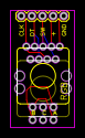
PCB
(
1
/
)
The preview image was not generated, please save it again in the
editor.
| ID | Name | Designator | Footprint | Quantity |
|---|---|---|---|---|
| 1 | M05 | JP1 | 1X05 | 1 |
| 2 | rotary encoder | SW1 | ENCODER_LED_3_KIT | 1 |
| 3 | M03 | JP2 | 1X03 | 1 |
Unfold
Project Members


 1
1
 3
3
Collect to album
Target complaint
Related Projects
Change a batch
Loading...
Add to album
×
Loading...
reminder
×
Do you need to add this project to the album?