


© 2024 EasyEDA Some rights reserved ISO/IEC
Editor Version
×
Standard

1.Easy to use and quick to get started
2.The process supports design scales of 300 devices or 1000 pads
3.Supports simple circuit simulation
4.For students, teachers, creators
Profession

1.Brand new interactions and interfaces
2.Smooth support for design sizes of over 5,000 devices or 10,000 pads
3.More rigorous design constraints, more standardized processes
4.For enterprises, more professional users
Ongoing
STD Blinking a Lamp
Mode: Editors' pick
- 0
Update time:
2021-04-11 09:28:03
Creation time:
2016-01-16 09:26:07
Description
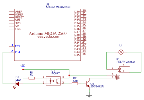
## Blinking a Lamp on and off ##
we have the relay clicking on and off. Inside, the COM terminal is connected to the NO (Normally Open) terminal when the relay is on. So all we have to do is use that switch to turn the lamp on and off.
![Blinking a Lamp on and off][1]
We're going to use a low-voltage lamp from IKEA, to make things a little safer. IF you wire this type
BlinkRelay2-450 relay to switch "Mains Voltage" (115V in USA and others, 220V in Europe and others) you MUST take precautions.
We will simply cut one side of the cable to the lamp, and route that connection through the relay from COM to NO.
You can use any of the Arduino I/O pins to drive a relay, because you will simply turn it ON or OFF.
![lamp][2]
Then in the main Loop section turn relays On or Off as needed... Following is an example program that properly controls 4 relays on our 4-relay board
**CODE**
/*-----( Import needed libraries )-----*/
/*-----( Declare Constants )-----*/
#define RELAY_ON 0
#define RELAY_OFF 1
/*-----( Declare objects )-----*/
/*-----( Declare Variables )-----*/
#define Relay_1  2  // Arduino Digital I/O pin number
#define Relay_2  3
#define Relay_3  4
#define Relay_4  5

void setup()   /****** SETUP: RUNS ONCE ******/
{
//-------( Initialize Pins so relays are inactive at reset)----
  digitalWrite(Relay_1, RELAY_OFF);
  digitalWrite(Relay_2, RELAY_OFF);
  digitalWrite(Relay_3, RELAY_OFF);
  digitalWrite(Relay_4, RELAY_OFF);

//---( THEN set pins as outputs )----
  pinMode(Relay_1, OUTPUT);
  pinMode(Relay_2, OUTPUT);
  pinMode(Relay_3, OUTPUT);
  pinMode(Relay_4, OUTPUT);
  delay(4000); //Check that all relays are inactive at Reset

}//--(end setup )---


void loop()   /****** LOOP: RUNS CONSTANTLY ******/
{
//---( Turn all 4 relays ON in sequence)---
  digitalWrite(Relay_1, RELAY_ON);// set the Relay ON
  delay(1000);              // wait for a second
  digitalWrite(Relay_2, RELAY_ON);// set the Relay ON
  delay(1000);              // wait for a second
  digitalWrite(Relay_3, RELAY_ON);// set the Relay ON
  delay(1000);              // wait for a second
  digitalWrite(Relay_4, RELAY_ON);// set the Relay ON
  delay(4000);              // wait see all relays ON

//---( Turn all 4 relays OFF in sequence)---
  digitalWrite(Relay_1, RELAY_OFF);// set the Relay OFF
  delay(1000);              // wait for a second
  digitalWrite(Relay_2, RELAY_OFF);// set the Relay OFF
  delay(1000);              // wait for a second
  digitalWrite(Relay_3, RELAY_OFF);// set the Relay OFF
  delay(1000);              // wait for a second
  digitalWrite(Relay_4, RELAY_OFF);// set the Relay OFF
  delay(4000);              // wait see all relays OFF


}//--(end main loop )---
Design Drawing
schematic diagram
(
1
/
)
PCB
(
1
/
)
The preview image was not generated, please save it again in the
editor.
| ID | Name | Designator | Footprint | Quantity |
|---|---|---|---|---|
| 1 | PC817 | U1 | NONE | 1 |
| 2 | 1k | R1 | R3 | 1 |
| 3 | LED | D1 | LED3MM | 1 |
| 4 | Arduino MEGA 2560 | U2 | DIP | 1 |
| 5 | 2DC2412R | Q1 | SOT23 | 1 |
| 6 | 510 | R2 | R3 | 1 |
| 7 | RELAY-V23092 | K1 | NONE | 1 |
| 8 | 1k | L1 | 1X02 | 1 |
Unfold
Project Members


 0
0
 0
0
Collect to album
Target complaint
Related Projects
Change a batch
Loading...
Add to album
×
Loading...
reminder
×
Do you need to add this project to the album?