


© 2024 EasyEDA Some rights reserved ISO/IEC
Editor Version
×
Standard

1.Easy to use and quick to get started
2.The process supports design scales of 300 devices or 1000 pads
3.Supports simple circuit simulation
4.For students, teachers, creators
Profession

1.Brand new interactions and interfaces
2.Smooth support for design sizes of over 5,000 devices or 10,000 pads
3.More rigorous design constraints, more standardized processes
4.For enterprises, more professional users
Ongoing
STD SparkFun Photon RedBoard
Mode: Editors' pick
- 1
Update time:
2021-04-12 08:29:50
Creation time:
2016-07-15 02:56:26
Description
![enter image description here][1]
![enter image description here][2]
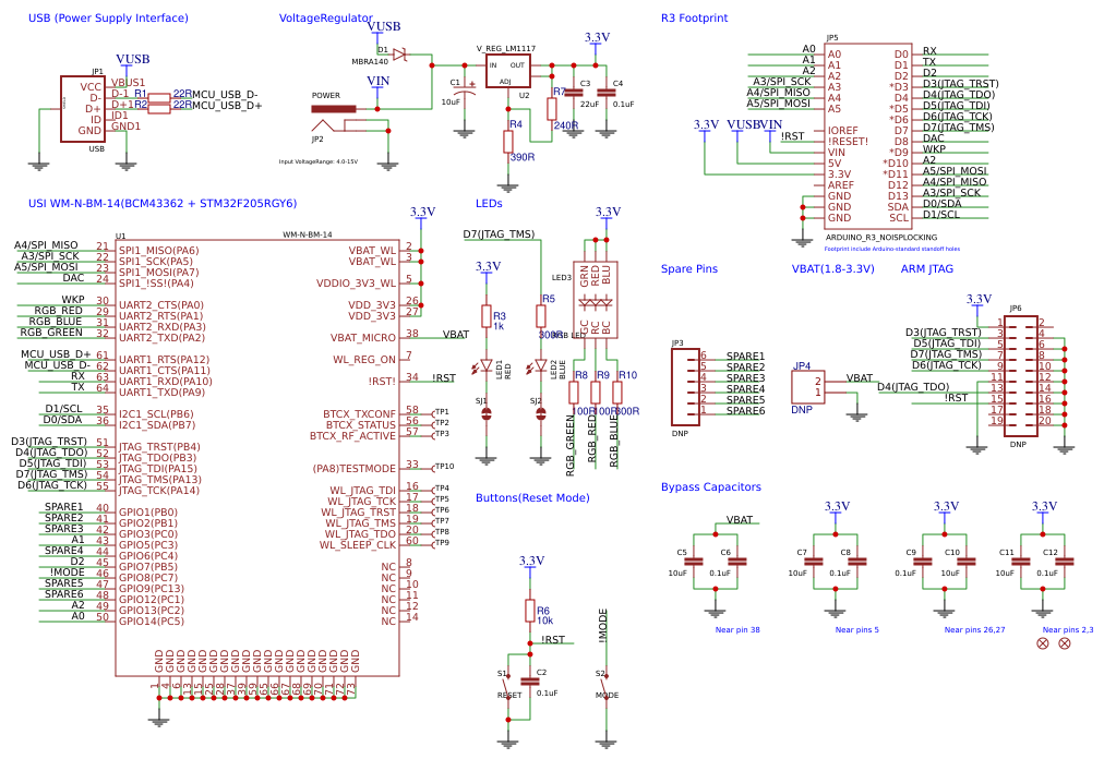
**Description:**
The SparkFun Photon RedBoard, to put it simply, is a WiFi/Microcontroller development board in the Arduino form-factor for the Photon. It’s easy to use, it’s powerful, and it’s connected to the cloud. With the best support, potential, and performance the Photon RedBoard provides you with an IoT device with a powerful 120MHz ARM Cortex M3 and built-in WiFi connectivity. Imagine blowing up a Photon into the shape of an Arduino and while keeping its wireless and ARM Cortex M3 capabilities, the result is this board!
The SparkFun Photon RedBoard has been based around the P1 Particle Module. Each P1 comes pre-loaded with Particle OS firmware and includes their basic cloud service. With a built-in antenna and a uFL connector, the P1 makes it so you don’t have to stress over the optimization of RF designs.
The Photon RedBoard has all of the hardware peripherals you know and love: 8 Digital I/O pins, 6 Analog Inputs, UART, SPI and ARM JTAG hook-ups. We’ve also broken out the SDA, SCL, SCK, MISO, MOSI, SS, DAC, and WKP pins as well. You can power the Photon RedBoard over USB or through the barrel jack. The on-board power regulator can handle anything from 4.5 to 15VDC. It is important to keep in mind that the Photon RedBoard utilizes the Arduino form factor, meaning you can attach many different Arduino shields to this board. Please be sure to check your pin-outs and voltage levels first.
**Features:**
STM32F205 120MHz ARM Cortex M3
1MB flash, 128KB RAM
Single band 2.4GHz IEEE 802.11b/g/n
Supports wireless data rates of up to 65Mbit/s
Ultra low power sleep, stand-by and stop modes
Supports Open, WEP, WAPI, WPA and WPA2-PSK WiFi security modes
Input voltage - 4.5-15V
8 Digital I/O Pins
6 Analog Inputs
ARM JTAG Hook-up
Arduino Form Factor
For more detail and Documents, Please visit: http://www.sparkfun.com/products/13321
[1]: /editor/20160717/578b4c752800c.png
[2]: /editor/20160717/578b4c7bc9909.png
Design Drawing
schematic diagram
(
1
/
)
PCB
(
1
/
)
The preview image was not generated, please save it again in the
editor.
| ID | Name | Designator | Footprint | Quantity |
|---|---|---|---|---|
| 1 | USB | JP1 | USB-B-MICRO-SMD_V03 | 1 |
| 2 | MBRA140 | D1 | SMA-DIODE | 1 |
| 3 | 0.1uF | C4,C2,C6,C8,C9,C12 | C-0603 | 6 |
| 4 | 10uF | C1 | EIA3216 | 1 |
| 5 | 22uF | C3 | C-0603 | 1 |
| 6 | POWER | JP2 | POWER_JACK_PTH_LOCK | 1 |
| 7 | RGB LED | LED3 | PLCC-6-LED | 1 |
| 8 | RESET | S1 | TACTILE-PTH | 1 |
| 9 | MODE | S2 | TACTILE-PTH | 1 |
| 10 | BLUE | LED2 | L-0603 | 1 |
| 11 | RED | LED1 | L-0603 | 1 |
| 12 | ARDUINO_R3_NOISPLOCKING | JP5 | ARDUINO_R3_NOISP_LOCKING | 1 |
| 13 | 10uF | C5,C7,C10,C11 | C-0603 | 4 |
| 14 | WM-N-BM-14 | U1 | WM-N-BM-14 | 1 |
| 15 | DNP | JP6 | 2X10 | 1 |
| 16 | DNP | JP3 | 1X06 | 1 |
| 17 | TEST-POINTTP_15TH_THRU | TP3,TP1,TP2,TP4,TP5,TP6,TP7,TP8,TP9,TP10 | TP_15TH | 10 |
| 18 | FIDUCIAL | FID2,FID1 | FIDUCIAL-1X2 | 2 |
| 19 | V_REG_LM1117 | U2 | SOT223 | 1 |
| 20 | PWR-LED | SJ1 | PAD-JUMPER-2-NC_BY_TRACE_YES_SILK | 1 |
| 21 | D7-LED | SJ2 | PAD-JUMPER-2-NC_BY_TRACE_YES_SILK | 1 |
| 22 | 10k | R6 | 3-0603 | 1 |
| 23 | DNP | JP4 | HDR1X2 | 1 |
| 24 | 100R | R8,R9 | 3-0603 | 2 |
| 25 | 300R | R10,R5 | 3-0603 | 2 |
| 26 | 1k | R3 | 3-0603 | 1 |
| 27 | 240R | R7 | 3-0603 | 1 |
| 28 | 390R | R4 | 3-0603 | 1 |
| 29 | 22R | R1,R2 | 3-0603 | 2 |
Unfold
Project Members


 0
0
 1
1
Collect to album
Target complaint
Related Projects
Change a batch
Loading...
Add to album
×
Loading...
reminder
×
Do you need to add this project to the album?