


© 2024 EasyEDA Some rights reserved ISO/IEC
Editor Version
×
Standard

1.Easy to use and quick to get started
2.The process supports design scales of 300 devices or 1000 pads
3.Supports simple circuit simulation
4.For students, teachers, creators
Profession

1.Brand new interactions and interfaces
2.Smooth support for design sizes of over 5,000 devices or 10,000 pads
3.More rigorous design constraints, more standardized processes
4.For enterprises, more professional users

Ongoing
STD Chipguy's Nano Breakout Board with Battery Power Control
Mode: Editors' pick
- 0
Update time:
2022-09-27 20:40:25
Creation time:
2020-11-08 18:10:45
Description
Add your own Arduino Nano, and enjoy the breakout!
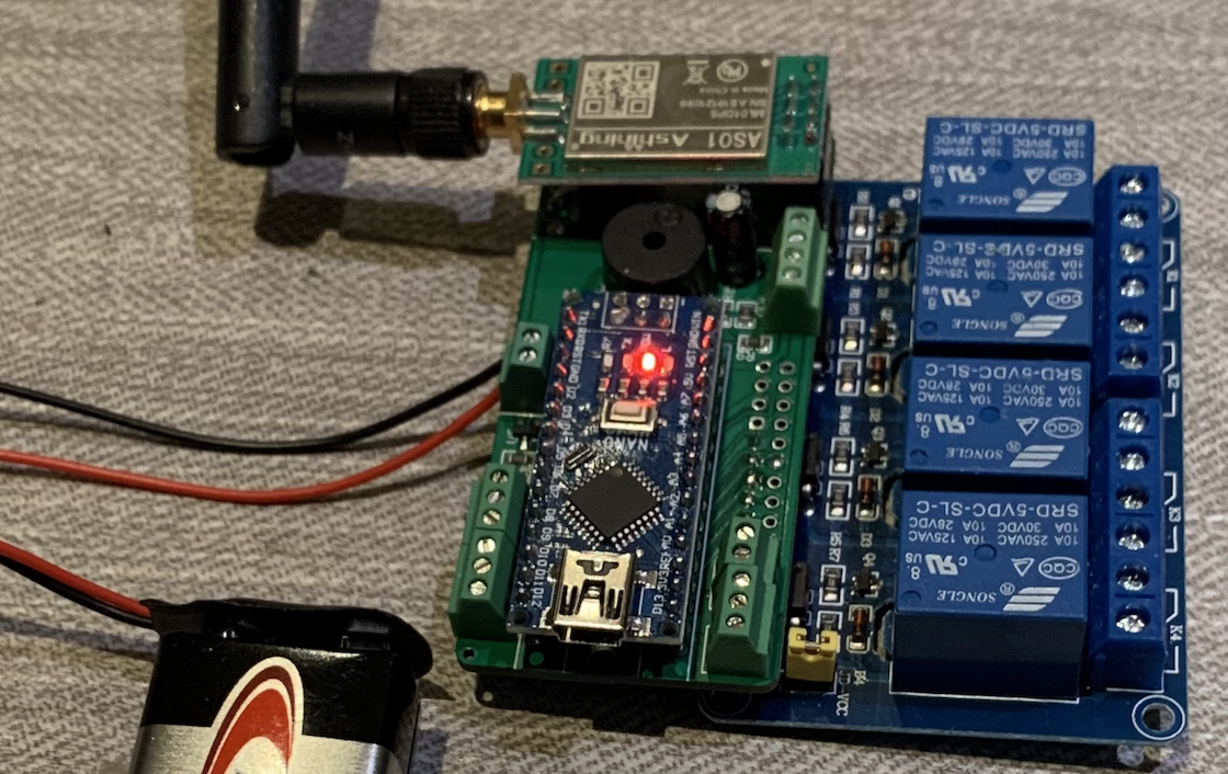

Power it via VIN(6-10V) or at the regulated 5V pin to keep it on full-time without power control.
Power it on via BAT+/- (6-10V) to enable battery power control, which allows you to completely cut off battery power until any PWBUTTON is pressed. This is not a charging system and is for non-rechargeable/alkaline batteries only. Power is switched on when you connect any of the five PWBUTTONS to their common (which happens to be BAT+). After button release, power stays on as long as your sketch holds D7 high.
You can read battery voltage via analogRead(A7). Range (0-1023) is 0-15V.
You can read the state of PWBUTTONS via A0,A1,A2,A3,A6 if you solder the pads on the underside of the board enabling this.
You can connect relays. The 10-pin headers along the side are meant to fit the 2, 4, and 8 blue relay packs made in China available on Amazon.
You can connect an NRF24L01 radio if you add a 100uF capacitor to C1. CSN/CE are D9/D10. IRQ select via solder pads.
Connect a piezo beeper, and send tones to it via tone() on D6.
Connect an IR receiver, and receive IR commands via D8.
Amazon sells a DS3231 real-time-clock that fits on the RTC pins and communicates over SDA/SCL.
If you want to exceed 11V at VIN (or use the power control to switch power for external loads bigger than a relay pack):
- remove U10 and replace it with an IRF9540N MOSFET (holes provided).
- If you want to bypass Nano's voltage regulator (especially at higher voltages) you may want to add a 5-volt DD4012SB buck converter (and cut VIN pin from your Nano), holes are provided for this.
- going above 15V? we'll overdrive Nano's pin A7 (voltage sense), cut that pin if going any higher than 15V.
Design Drawing
schematic diagram
(
1
/
)
PCB
(
1
/
)
The preview image was not generated, please save it again in the
editor.
BOM
Project Members


 0
0
 0
0
Collect to album
Related Projects
Change a batch
Loading...
Add to album
×
Loading...
reminder
×
Do you need to add this project to the album?