


© 2024 EasyEDA Some rights reserved ISO/IEC
Editor Version
×
Standard

1.Easy to use and quick to get started
2.The process supports design scales of 300 devices or 1000 pads
3.Supports simple circuit simulation
4.For students, teachers, creators
Profession

1.Brand new interactions and interfaces
2.Smooth support for design sizes of over 5,000 devices or 10,000 pads
3.More rigorous design constraints, more standardized processes
4.For enterprises, more professional users
Ongoing
STD MOSFET Power Controller (Open hardware)
Mode: Editors' pick
- 1
Update time:
2021-04-11 18:20:17
Creation time:
2015-12-22 02:24:32
Description
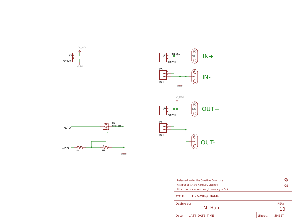
Description: MOSFETs are awesome. They’re like a switch that you flip electronically! This SparkFun MOSFET Power Controller makes it easy to switch a battery supply on and off using your favorite microcontroller. The board also has sewable pads so you can use it in e-textile projects that need more juice.
The MOSFET Power Controller came about because microcontrollers, like the Arduino or LilyPad Arduino, can only supply a limited amount of current. Sometimes, though, you want to control something that takes a lot of current like a fan or a heater (or a really bright LED). Simply connect a battery to the JST connector on the MOSFET Power Controller, connect the thing that needs power to the output, then connect one of the digital outputs of your microcontroller to the input pads. Now whenever you drive that pin on your controller HIGH, the battery will be connected!
The N-Channel MOSFET used in this design is rated for up to 30V and 6.5A although the board is really intended to be used at lower power. If you hook up anything beyond a 3.7V Li-Po battery, proceed at your own risk!
Features:
Control High-Current Loads
JST Connector makes Changing Batteries a Snap
It’s Sewable! (Also has standard 0.1" spaced headers)
[GitHub][1] (Design Files)
Sparkfun link:https://www.sparkfun.com/products/11214
![enter image description here][2]
[1]: https://github.com/sparkfun/MOSFET_Power_Controller/tree/V_1.0
[2]: /editor/20151231/5684c80e572b7.png
Design Drawing
schematic diagram
(
1
/
)
PCB
(
1
/
)
The preview image was not generated, please save it again in the
editor.
| ID | Name | Designator | Footprint | Quantity |
|---|---|---|---|---|
| 1 | FRAME-LETTER | FRAME1 | CREATIVE_COMMONS | 1 |
| 2 | JST-SMT | JP1 | JST-2-SMD | 1 |
| 3 | JST-PTH | JP3,JP4 | JST-2-PTH-NS | 2 |
| 4 | TRIG+ | BH1 | BUTTONHOLE | 1 |
| 5 | TRIG- | BH2 | BUTTONHOLE | 1 |
| 6 | OUT+ | BH3 | BUTTONHOLE | 1 |
| 7 | OUT- | BH4 | BUTTONHOLE | 1 |
| 8 | 10k | R1 | 0402-RES | 1 |
| 9 | 1M | R2 | 0402-RES | 1 |
| 10 | FDS6630A | Q1 | SO08 | 1 |
| 11 | M02 | JP2,JP5 | 1X02 | 2 |
| 12 | FIDUCIAL | JP6,JP7 | MICRO-FIDUCIAL | 2 |
Unfold
Project Members


 0
0
 1
1
Collect to album
Target complaint
Related Projects
Change a batch
Loading...
Add to album
×
Loading...
reminder
×
Do you need to add this project to the album?