


© 2024 EasyEDA Some rights reserved ISO/IEC
Editor Version
×
Standard

1.Easy to use and quick to get started
2.The process supports design scales of 300 devices or 1000 pads
3.Supports simple circuit simulation
4.For students, teachers, creators
Profession

1.Brand new interactions and interfaces
2.Smooth support for design sizes of over 5,000 devices or 10,000 pads
3.More rigorous design constraints, more standardized processes
4.For enterprises, more professional users
Ongoing
STD Spectrum Shield (Open hardware)
Mode: Editors' pick
- 2
Update time:
2021-04-09 05:53:41
Creation time:
2015-12-22 02:40:42
Description
Description: The Spectrum Shield enables your Arduino with the capability of splitting a stereo audio input into 7-bands per channel. You can then read the amplitude of each channel using the ADC on your Arduino allowing you to control everything from LEDs to motors, pumps to relays, or even fire, all with sound. With this shield you will be able to have almost any project be able to react to music or sound!
The Spectrum Shield features the MSGEQ7 graphic equalizer display filter. Two of these ICs allow you to split a stereo audio input into 7-bands (per channel) and read the amplitude of each using the ADC on your Arduino. The shield is populated with two 1/8" stereo jacks (like you would find on a pair of headphones). One serves as a stereo input and the other is a pass-through output which allows you to connect the Spectrum Shield in-line between your audio source and your stereo system without interruption. This revision of the Spectrum Shield has been updated to the Arduino R3 layout but still requires you to solder on your own headers (check the Recommended Products section below). This shield can be used to create sound visualizers, detect patterns in music or add sound activation to your microcontroller projects.
[GitHub][1] (Example Code & Design Files)
Sparkfun link:https://www.sparkfun.com/products/13116
![enter image description here][2]
[1]: https://github.com/sparkfun/Spectrum_Shield/tree/HW_1.5_FW_1.0
[2]: /editor/20151231/5684c36c40d0e.png
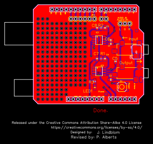
Design Drawing
schematic diagram
(
1
/
)
PCB
(
1
/
)
The preview image was not generated, please save it again in the
editor.
| ID | Name | Designator | Footprint | Quantity |
|---|---|---|---|---|
| 1 | 1000pF | C1,C3 | 0603-CAP | 2 |
| 2 | 33pF | C2,C4 | 0603-CAP | 2 |
| 3 | 0.1uF | C6,C8,C5,C7 | 0603-CAP | 4 |
| 4 | 200k | R2,R1 | 0603-RES | 2 |
| 5 | JUMPER-3 | AUDIO_IN | 1X03 | 1 |
| 6 | ARDUINO_R3_SHIELD | U1 | UNO_R3_SHIELD | 1 |
| 7 | FRAME-LETTER | FRAME1 | CREATIVE_COMMONS | 1 |
| 8 | 330 | R3 | 0603-RES | 1 |
| 9 | RED | LED1 | LED-0603 | 1 |
| 10 | M02 | JP2 | 1X02 | 1 |
| 11 | M06 | JP3 | 1X06 | 1 |
| 12 | TAC_SWITCH | S1 | TACTILE_SWITCH_SMD | 1 |
| 13 | MSGEQ7 | IC1,IC2 | SOIC8 | 2 |
| 14 | FIDUCIAL | JP4,JP5 | FIDUCIAL-1X2 | 2 |
| 15 | AUDIO-JACK | AUDIOJACK1,AUDIOJACK2 | AUDIO-JACK-3.5MM-SMD | 2 |
| 16 | OSHW-LOGOM | LOGO1 | OSHW-LOGO-M | 1 |
| 17 | SFE_LOGO_FLAME.2_INCH | LOGO2 | SFE_LOGO_FLAME_.2 | 1 |
| 18 | SFE_LOGO_NAME_FLAME | LOGO3 | SFE_LOGO_NAME_FLAME_.1 | 1 |
Unfold
Project Members


 0
0
 2
2
Collect to album
Target complaint
Related Projects
Change a batch
Loading...
Add to album
×
Loading...
reminder
×
Do you need to add this project to the album?