


© 2024 EasyEDA Some rights reserved ISO/IEC
Editor Version
×
Standard

1.Easy to use and quick to get started
2.The process supports design scales of 300 devices or 1000 pads
3.Supports simple circuit simulation
4.For students, teachers, creators
Profession

1.Brand new interactions and interfaces
2.Smooth support for design sizes of over 5,000 devices or 10,000 pads
3.More rigorous design constraints, more standardized processes
4.For enterprises, more professional users
Ongoing
STD Lamp dimmer using NE555
Mode: Editors' pick
- 0
Update time:
2021-04-11 13:53:35
Creation time:
2015-09-07 08:32:03
Description
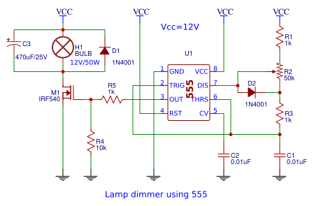
**Lamp dimmer using NE555.**
This project is about simple lamp dimmer project using NE555 timer IC. PWM method is used for controlling the brightness of the lamp. This method is very power efficient and low cost compared to linear power control circuits. In PWM method the load is driven using a high frequency square wave and the duty cycle of this square wave is varied for controlling the power delivered to the load. The efficiency of this circuit was found to be 95.5% when tested in the lab. The same circuit can be also used to control the speed of DC motors.
**Working of the circuit.**
This circuit is basically an astable multivibrator with variable duty cycle using NE555 timer IC. The frequency is determined by using the equation F=1/(0.69(R1+2R2+R3)C1). With the components used, the base frequency of the circuit is 2.75KHz. The duty cycle and hence the brightness of the lamp can be controlled by varying the POT R3. Capacitor C2 by-passes the lower half of the POT R3 when timing capacitor C1 is charged. The base frequency will be constant irrespective of the position of R3 and the duty cycle only changes.
Capacitor C2 is meant for noise shunting. MOSFET IRF540 is used for switching the lamp according to the PWM output from the timer IC. The PWM output is connected to the gate of the MOSFET using resistor R5. R4 is a pull-down resistor. The load, ie; the bulb is connected to the drain of the MOSFET. C3 is filter capacitor which smooths the switched PWM waveform across the load. D1 is a freewheeling diode. This diode is not needed for an incandescent lamp because it produces no back emf during switching. But it is included in the circuit as a precaution in case you use inductive loads like motors. You can also control the brightness of 12V LED strings using this circuit. What ever may be the load, one thing you have to keep in mind is that the load current must not exceed the current rating of the MOSFET. Here the current rating of IRF540 is around 22A.
![enter image description here][1]
[1]: /editor/20150910/55f0619490ac0.png
Design Drawing
schematic diagram
(
1
/
)
PCB
(
1
/
)
The preview image was not generated, please save it again in the
editor.
| ID | Name | Designator | Footprint | Quantity |
|---|---|---|---|---|
| 1 | 555 | U1 | DIP08 | 1 |
| 2 | 1k | R1,R3,R5 | R3 | 3 |
| 3 | 50k | R2 | TRIM_POT_PTH | 1 |
| 4 | 0.01uF | C2,C1 | C1 | 2 |
| 5 | IRF540 | M1 | SOT23 | 1 |
| 6 | 10k | R4 | R3 | 1 |
| 7 | BULB | H1 | IND2-N10 | 1 |
| 8 | 1N4001 | D1,D2 | DO35-7 | 2 |
| 9 | 470uF/25V | C3 | CP_8X13MM | 1 |
| 10 | TL071 | U1,U2 | NONE | 2 |
| 11 | 100k | R1,R2 | R3 | 2 |
| 12 | 2.2k | R3 | R3 | 1 |
| 13 | 470n | C1 | C1 | 1 |
| 14 | Audio IN | J1 | CONNECTOR_2P-2.54 | 1 |
| 15 | 100k | R4,R9,R12 | TRIM_POT_PTH | 3 |
| 16 | 18k | R5,R6 | R3 | 2 |
| 17 | 4.7k | R7,R8 | R3 | 2 |
| 18 | 22n | C2,C3 | C1 | 2 |
| 19 | 4.7n | C4,C5 | C1 | 2 |
| 20 | 15k | R10,R11 | R3 | 2 |
| 21 | 10u | C6,C11 | CP_8X13MM | 2 |
| 22 | TDA2003H | U3 | TO | 1 |
| 23 | 470u | C7 | CP_8X13MM | 1 |
| 24 | 220R | R13 | R3 | 1 |
| 25 | 10R | R14 | R3 | 1 |
| 26 | 1n | C8 | C1 | 1 |
| 27 | 2200u | C9 | CP_8X13MM | 1 |
| 28 | 100n | C10 | C1 | 1 |
| 29 | 1R | R15 | R3 | 1 |
| 30 | 8R | SPK | 1X02 | 1 |
| 31 | 100u | C12 | CP_8X13MM | 1 |
Unfold
Project Members


 0
0
 0
0
Collect to album
Target complaint
Related Projects
Change a batch
Loading...
Add to album
×
Loading...
reminder
×
Do you need to add this project to the album?