© 2024 EasyEDA Some rights reserved ISO/IEC
Editor Version
×
Standard


1.Easy to use and quick to get started
2.The process supports design scales of 300 devices or 1000 pads
3.Supports simple circuit simulation
4.For students, teachers, creators
Profession


1.Brand new interactions and interfaces
2.Smooth support for design sizes of over 5,000 devices or 10,000 pads
3.More rigorous design constraints, more standardized processes
4.For enterprises, more professional users

Completed
STD Crosstalk Project
License: MIT License
Mode: Editors' pick
- 0
Update time:
2024-03-22 12:01:06
Creation time:
2023-11-10 10:56:17
Description
Features
- Active Oscillator for driving the Buffer
- 8 Independent Aggressor Lines
- 7 Silent Lines with 10-bit ADCs
- Standard Arduino functionality for capturing ADC readings
- Powered by USB
- Test Pads
- GND Pins for connecting Oscilloscope probes
- 3 Jumpers to select the captured ADC line
- BNC connectors for direct connection of Waveform Generator and Oscilloscope
- Additional PC Application for real-time histogram plotting (via COM-port)
Details
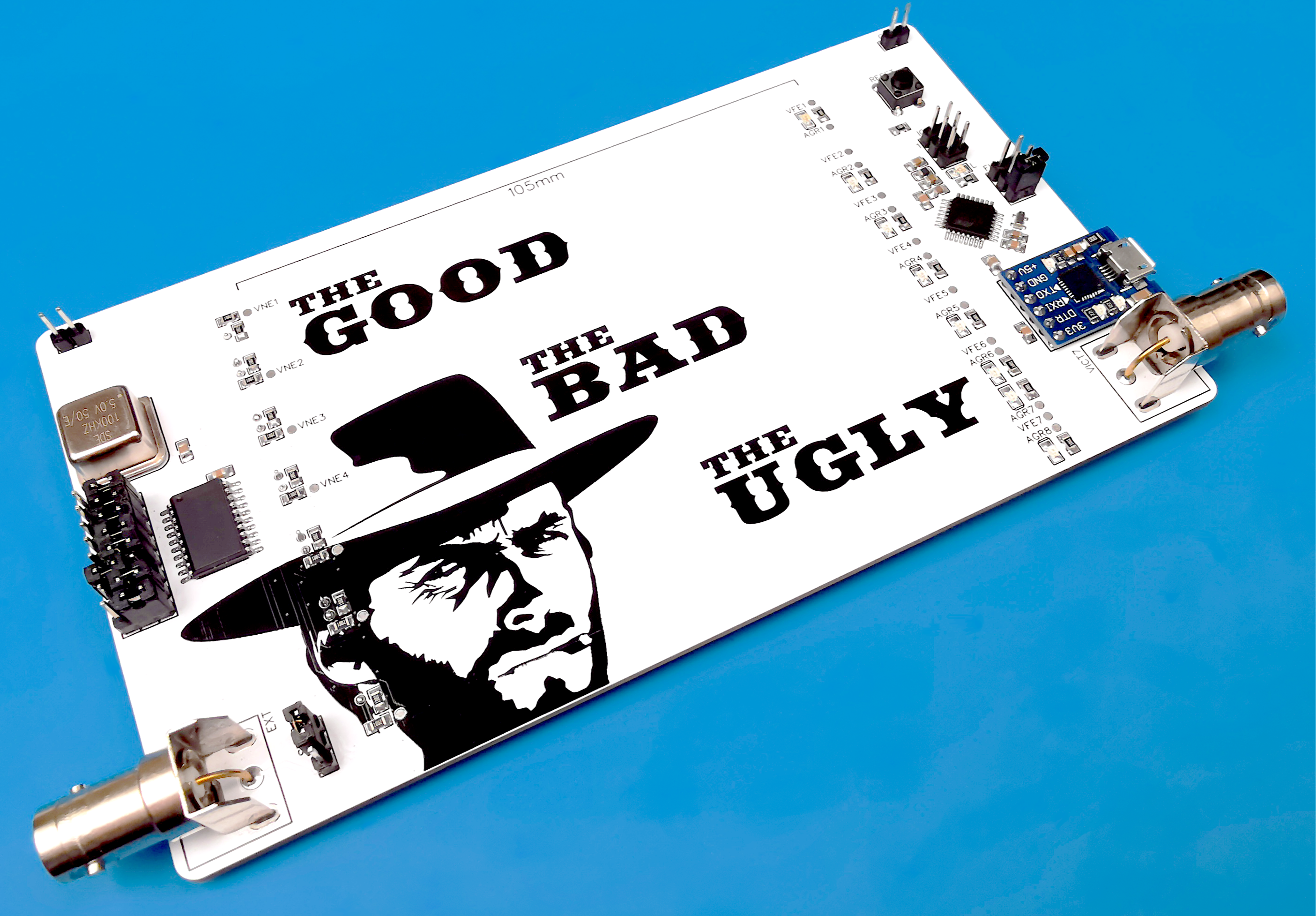
The board contains a 100 kHz quartz oscillator, the output of which can be fed through separate jumpers to the inputs of an 8-channel buffer and further to the transmission lines ending in a pair of resistor/LED. The buffer output rise time (10%-90%) is approximately 1.24ns (depends on the certain chip exemplar). Next to each active transmission line, there is a quiet line connected to the ADC input of ATmega328P.
The board can be used to study the dependence of crosstalk, as well as EMI, on the distance between active lines and the ground layer. There are 7 options on the board for the location of the aggressor/victim relative to each other and relative to the ground:
- The tracks are far from each other (4 times the thickness of the board), ground bottom layer and additional coplanar ground poured on the top layer.
- The same, but the tracks are at a distance equal to the thickness of the board (1H).
- The distance is 1H and the ground is only coplanar.
- The distance is 1H and the ground is only on the bottom layer.
- 1H and there is no ground at all.
- 0.254mm w/o ground.
- 0.254mm, no ground, but there are 2 aggressors on both sides of the victim.
Below are the values of crosstalk (peak-to-peak) measured by microcontroller's ADC:

The FUNC jumper is used to select one of the seven quiet lines. After powering on/resetting, the microcontroller will establish a COM-port connection at 115200 bps and will continuously transmit the ADC readings of the selected line. Each transmitted value followed with the symbol LF ('\n'). In addition, the microcontroller periodically transmits the supply voltage, the average value of the ADC readings for the selected line and the ADC resolution using the following commands (see Arduino sketch):
  Serial.print("Vref:\t");
  Serial.println(vRef, 4);

  Serial.print("Average:\t");
  Serial.println(averageValue, 8);

  Serial.print("ADCres:\t");
  Serial.println("10");
If none of the lines is selected, the microcontroller calibrates the average ADC values for each of the lines and stores them in the EEPROM.
The microcontroller can be programmed as a regular Arduino Nano via USB, or if the microcontroller is new and does not contain a bootloader, then via ICSP (pinout is similar to Arduino Nano).
Links
Additional project files (+ Arduino sketch) - https://drive.google.com/drive/folders/1W1JLNsPT2SEZL56siSkae4JzRNmqcd-y
PC Application for real-time histogram plotting - https://github.com/DmitryMuravyev/Serial-To-Histogram
ATmega328P Datasheet - https://ww1.microchip.com/downloads/en/DeviceDoc/Atmel-7810-Automotive-Microcontrollers-ATmega328P_Datasheet.pdf
74AC541 Datasheet - https://www.onsemi.com/pdf/datasheet/74act541-d.pdf
Components
MCU ATmega328P - https://ali.ski/Lv3ZNe
СP2102 UART-USB Module - https://ali.ski/TGgDhr
Ceramic Resonator with Built-in Capacitors Murata 16MHz - https://ali.ski/cmpEn
Tactile Push Button - https://ali.ski/BK0MYV
SMD LED Kit - https://ali.ski/B3TZXm
SMD Capacitor Sample Book - https://ali.ski/l-lE9
SMD Resistor Sample Book - https://ali.ski/6YxlCV
SMD Inductor Sample Book - https://fas.st/_F2R0q
Single Row 2.54 Header - https://fas.st/rEcmD
Three Row 2.54 Header - https://fas.st/w2IHC4
2.54mm Jumper - https://ali.ski/XfxtVj
PCB Mount BNC Connector, 50 Ohms - https://ali.ski/V55riP
Design Drawing
schematic diagram
(
1
/
)
PCB
(
1
/
)
The preview image was not generated, please save it again in the
editor.
BOM
Project Members
Related Projects
Change a batch
Loading...
Add to album
×
Loading...
reminder
×
Do you need to add this project to the album?


