


© 2024 EasyEDA Some rights reserved ISO/IEC
Editor Version
×
Standard

1.Easy to use and quick to get started
2.The process supports design scales of 300 devices or 1000 pads
3.Supports simple circuit simulation
4.For students, teachers, creators
Profession

1.Brand new interactions and interfaces
2.Smooth support for design sizes of over 5,000 devices or 10,000 pads
3.More rigorous design constraints, more standardized processes
4.For enterprises, more professional users
Ongoing
STD ATtiny412 BatteryCapacityTester
License: CC-BY-SA 3.0
Mode: Editors' pick
- 6
Update time:
2022-08-20 08:06:49
Creation time:
2022-08-01 18:56:06
Description
# Overview
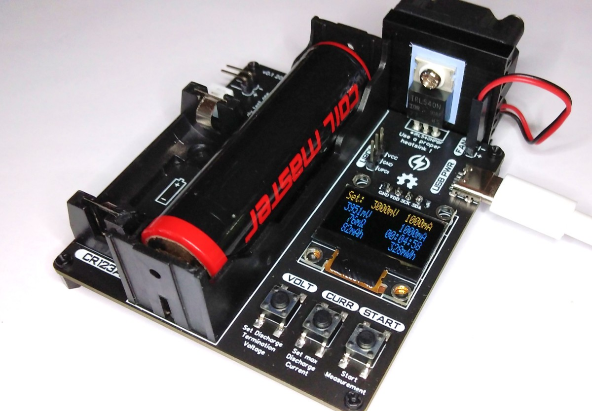
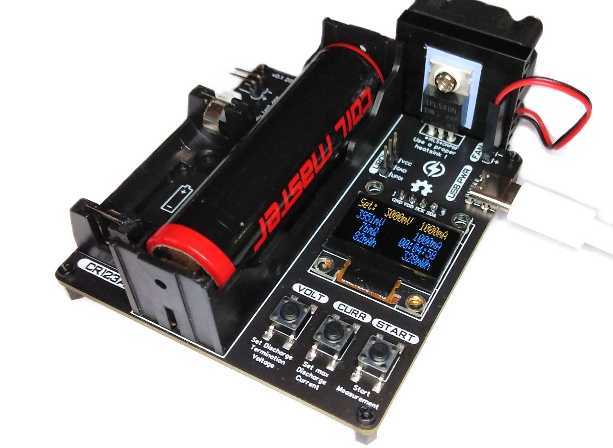
The ATtiny412 controlled battery capacity tester measures the capacity of single-cell Li-Ion, LiPo and LiFePO4 batteries using the built-in constant current load. Discharge termination (cutoff) voltage and discharge current can be selected by the user. During the discharging process, all relevant data is displayed on an OLED.
- Firmware (Github): https://github.com/wagiminator/ATtiny412-BatteryCapacityTester
# Hardware
## Schematic
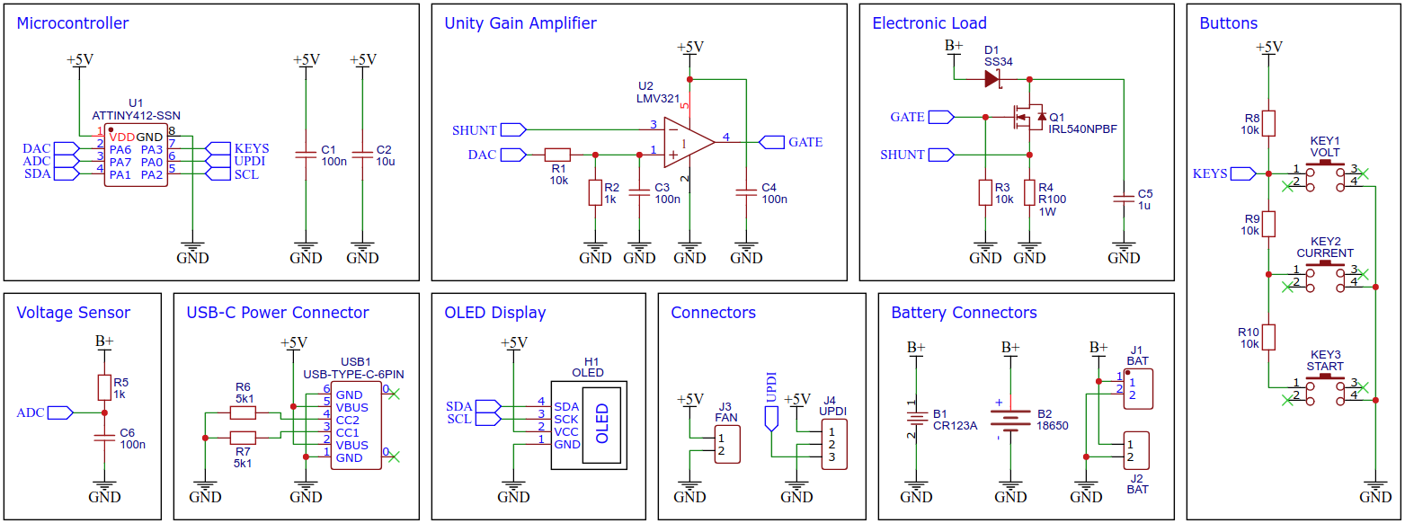
## Electronic Load
The electronic load control circuit, which essentially consists of an operational amplifier, a MOSFET and a shunt resistor, ensures that the same current flows regardless of the voltage applied.
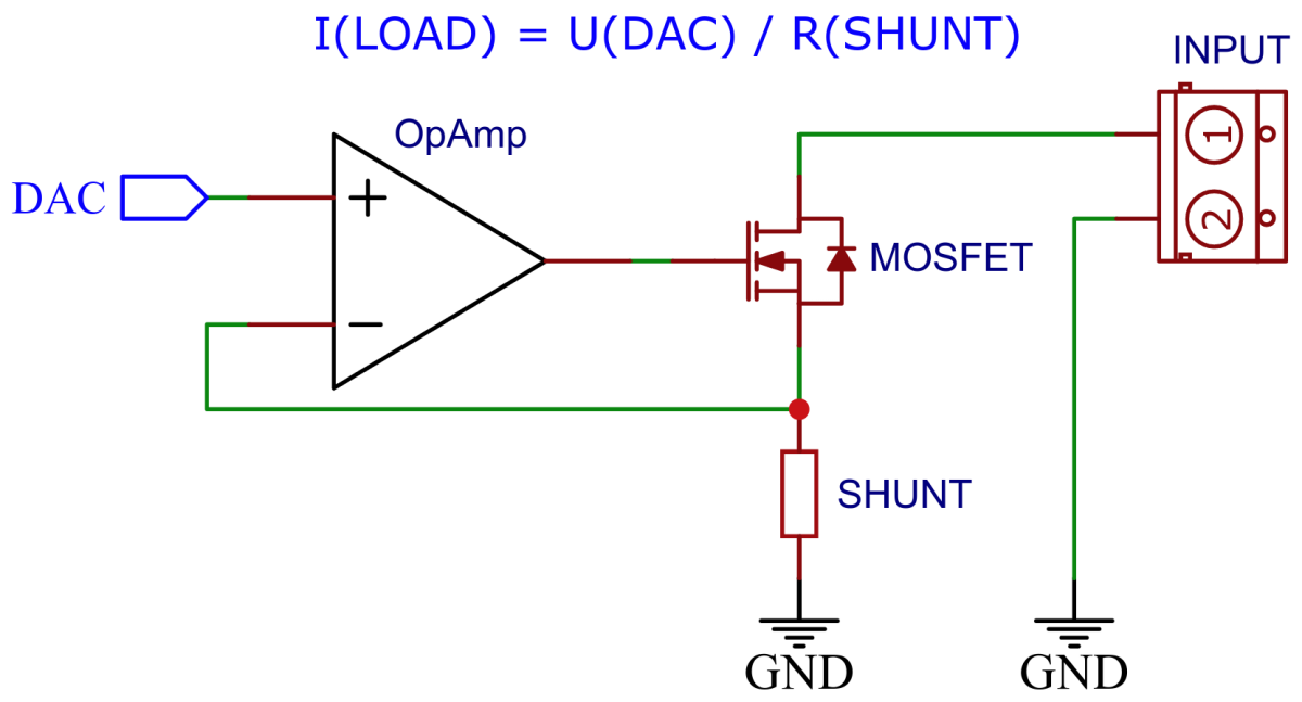
For this purpose, a 100mΩ/1W shunt resistor is located in the load circuit, via which the current is measured. The [LMV321](https://www.onsemi.com/pdf/datasheet/lmv321-d.pdf) rail-to-rail OpAmp compares this with the target value, which is specified by the ATtiny's internal digital to analog converter (DAC) via a voltage divider and accordingly controls the gate of an [IRL540N](https://datasheet.lcsc.com/lcsc/1808281632_Infineon-Technologies-IRL540NPBF_C111607.pdf) logic level n-channel power MOSFET, which in turn adjusts the current through its internal resistance set in this way.
# Software
## Operating Principle
The ATtiny412 controls the electronic dummy load with its internal digital to analog converter (DAC). All of its 5 internal reference voltages are being used in order to get the maximum accuracy and resolution of the DAC. The DAC is connected to an OpAmp which acts as a unity gain amplifier controlling the resistance of the MOSFET.
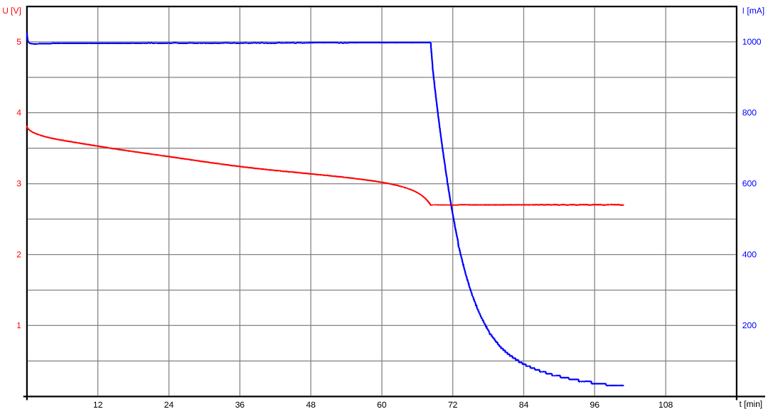
After pressing the START button the device measures the battery voltage without load via the ATtiny's analog to digital converter (ADC). Then it sets a constant current load with the selected maximum discharge current and measures the battery voltage again. The internal resistance of the battery is calculated from the voltage drop and the discharge current. During the discharging process, the battery voltage is measured regularly and the time is measured via the timer (TCB). In conjunction with the known discharge current, the charge drawn and ultimately the capacity of the battery can be determined. If the voltage drops below the selected discharge termination voltage the device constantly decreases the load to maintain this voltage. It stops automatically if the load current drops to 0mA. The voltage and current curve of a discharge cycle is illustrated in the graph below (discharge termination voltage: 2700mV, max discharge current: 1000mA):
If a continuous reduction in the discharge current at the end of the discharge process is not desired, this can be set in the firmware parameters.
## Firmware Parameters
Before compiling the firmware, some parameters can be adjusted to suit user behavior.
```c
// Firmware parameters
#define VOLT_MIN 2500 // minimum selectable termination voltage
#define VOLT_MAX 3200 // maximum selectable termination voltage
#define VOLT_STEP 100 // voltage selection steps
#define VOLT_START 3000 // voltage start value
#define CURR_MIN 200 // minimum selectable load current
#define CURR_MAX 2000 // maximum selectable load current
#define CURR_STEP 200 // current selection steps
#define CURR_START 200 // current start value
#define CYCLE_END 1 // 0-stop immediately, 1-decrease load
```
## Compiling and Uploading the Firmware
### If using the Arduino IDE
- Open your Arduino IDE.
- Make sure you have installed [megaTinyCore](https://github.com/SpenceKonde/megaTinyCore).
- Go to **Tools -> Board -> megaTinyCore** and select **ATtiny412/402/212/202**.
- Go to **Tools** and choose the following board options:
- **Chip:** ATtiny412
- **Clock:** 5 MHz internal
- Leave the rest at the default settings.
- Connect your programmer to your PC and to the UPDI header on the board.
- Go to **Tools -> Programmer** and select your [UPDI programmer](https://github.com/wagiminator/AVR-Programmer).
- Go to **Tools -> Burn Bootloader** to burn the fuses.
- Open the sketch and click **Upload**.
### If using the makefile (Linux/Mac)
- Download [AVR 8-bit Toolchain](https://www.microchip.com/mplab/avr-support/avr-and-arm-toolchains-c-compilers) and extract the sub-folders (avr, bin, include, ...) to /software/tools/avr-gcc. To do this, you have to register for free with Microchip on the download site.
- Open a terminal.
- Navigate to the folder with the makefile and the sketch.
- Run `PROGRMR=serialupdi PORT=/dev/ttyUSB0 make install` to compile, burn the fuses and upload the firmware (change PROGRMR and PORT accordingly).
# Operating Instructions
## Measurement Process
1. Connect the device to a 5V power supply via the USB-C port.
2. Use the buttons to select the discharge termination voltage and the maximum discharge current.
3. Connect the previously fully charged battery to be tested to the device.
4. Press the START button.
5. Wait for the discharging process to finish. The capacity can now be read.
6. Remove the battery afterwards and press any key.
## Selecting the appropriate Discharge Termination (Cutoff) Voltage
The discharge termination voltage should not be selected below 2700mA for Li-Ion or LiPo batteries, or below 2000mA for LiFePO4 batteries, in order to avoid deep discharge and damage to the battery. The recommended discharge termination voltage is 3200mA for Li-Ion and LiPo batteries and 2500mA for LiFePO4 batteries, since around 95% of the capacity is already used here and this also protects the battery. Keep in mind that batteries with a built-in protection circuit can interrupt the discharge process beforehand. The battery voltage may rise again after the discharge process is finished.
## Selecting the appropriate Maximum Discharge Current
Check the battery's data sheet for its maximum discharge current. If this is not known, then discharge the battery with a maximum of 1C (e.g. a 400mAh battery with a maximum of 400mA). Since the battery voltage drops as the load increases, it can make sense to choose the discharge current according to the intended application for the battery.
## Safety Instructions
- The device is designed for a maximum discharge current of 3000mA. This should never be exceeded!
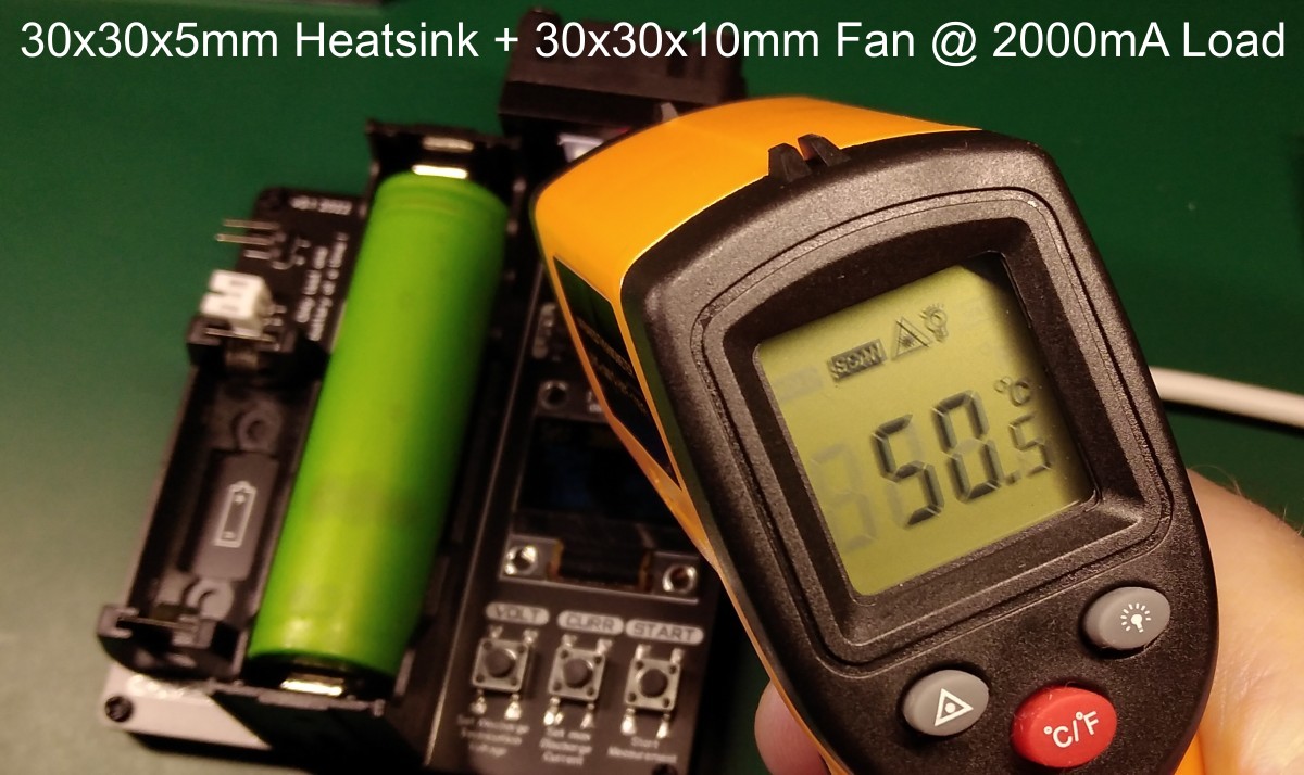
- The higher the selected discharge current, the better the cooling for the MOSFET should be. If necessary, the cooling should be actively supported by a 5V fan. Check the temperature of the MOSFET when you use it for the first time.
- Only use the device under supervision!
- Only use single-cell Li-Ion, LiPo or LiFePO4 batteries!
- Only connect one battery to the device at a time!
- Do not use damaged batteries!
- Pay attention to the correct polarity when connecting the battery to the device!
- Remove the battery immediately after discharging, as small currents may continue to flow.
# References, Links and Notes
1. [ATtiny814 Power Analyzer](https://github.com/wagiminator/ATtiny814-Power-Analyzer)
2. [ATtiny412 Datasheet](https://ww1.microchip.com/downloads/aemDocuments/documents/MCU08/ProductDocuments/DataSheets/ATtiny212-214-412-414-416-DataSheet-DS40002287A.pdf)
3. [LMV321 Datasheet](https://www.onsemi.com/pdf/datasheet/lmv321-d.pdf)
4. [IRL540N Datasheet](https://datasheet.lcsc.com/lcsc/1808281632_Infineon-Technologies-IRL540NPBF_C111607.pdf)
# License

This work is licensed under Creative Commons Attribution-ShareAlike 3.0 Unported License.
(http://creativecommons.org/licenses/by-sa/3.0/)
Design Drawing
schematic diagram
(
1
/
)
PCB
(
1
/
)
The preview image was not generated, please save it again in the
editor.
| ID | Name | Designator | Footprint | Quantity |
|---|---|---|---|---|
| 1 | CR123A | B1 | TH_L43.0-W-18.0-CR123A | 1 |
| 2 | 18650 | B2 | BH-18650-A | 1 |
| 3 | 100n | C1,C3,C4,C6 | C_0603 | 4 |
| 4 | 10u | C2 | C_0603 | 1 |
| 5 | 1u | C5 | C_0603 | 1 |
| 6 | SS34 | D1 | DIODE-SMA(DO-214AC) | 1 |
| 7 | OLED | H1 | I2C OLED 0.96 NEW | 1 |
| 8 | BAT | J1 | CONN-TH_2P-P2.00_PH-2AW | 1 |
| 9 | BAT | J2 | HEADER_2X1 | 1 |
| 10 | FAN | J3 | HEADER_2X1 | 1 |
| 11 | UPDI | J4 | 210S-3X1/2.54 | 1 |
| 12 | VOLT | KEY1 | KEY-6.0*6.0 | 1 |
| 13 | CURRENT | KEY2 | KEY-6.0*6.0 | 1 |
| 14 | START | KEY3 | KEY-6.0*6.0 | 1 |
| 15 | IRL540NPBF | Q1 | TO-220-3_L10.0-W4.5-P2.54-T | 1 |
| 16 | 10k | R1,R3,R8,R9,R10 | 0603 | 5 |
| 17 | 1k | R2,R5 | 0603 | 2 |
| 18 | R100 | R4 | 2512 | 1 |
| 19 | 5k1 | R6,R7 | 0603 | 2 |
| 20 | ATTINY412-SSN | U1 | SOP-8_150MIL | 1 |
| 21 | LMV321 | U2 | SOT-23-5_BR | 1 |
| 22 | USB-TYPE-C-6PIN | USB1 | USB-C-SMD-6P | 1 |
Unfold
Project Members


 5
5
 6
6
Collect to album
Target complaint
Related Projects
Change a batch
Loading...
Add to album
×
Loading...
reminder
×
Do you need to add this project to the album?