


© 2024 EasyEDA Some rights reserved ISO/IEC
Editor Version
×
Standard

1.Easy to use and quick to get started
2.The process supports design scales of 300 devices or 1000 pads
3.Supports simple circuit simulation
4.For students, teachers, creators
Profession

1.Brand new interactions and interfaces
2.Smooth support for design sizes of over 5,000 devices or 10,000 pads
3.More rigorous design constraints, more standardized processes
4.For enterprises, more professional users

Ongoing
STD ATtiny814 NRF2USB
License: CC-BY-SA 3.0
Mode: Editors' pick
- 7
Update time:
2023-02-22 18:19:57
Creation time:
2021-05-14 08:58:45
Description
# Overview
NRF2USB is a simple development tool for wireless applications based on the nRF24L01+ 2.4GHz transceiver module. It provides a serial interface for communication with the module via USB. The CH330N (or CH340N) USB to serial chip can also function as a SerialUPDI programmer for the integrated ATtiny814 (or compatible), so that no external programming device is necessary.
- Firmware (Github): https://github.com/wagiminator/ATtiny814-NRF2USB
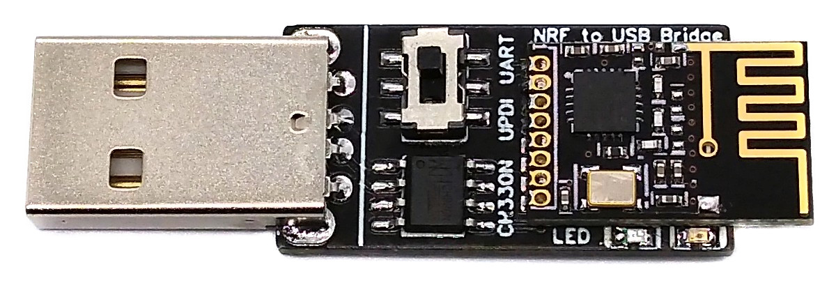
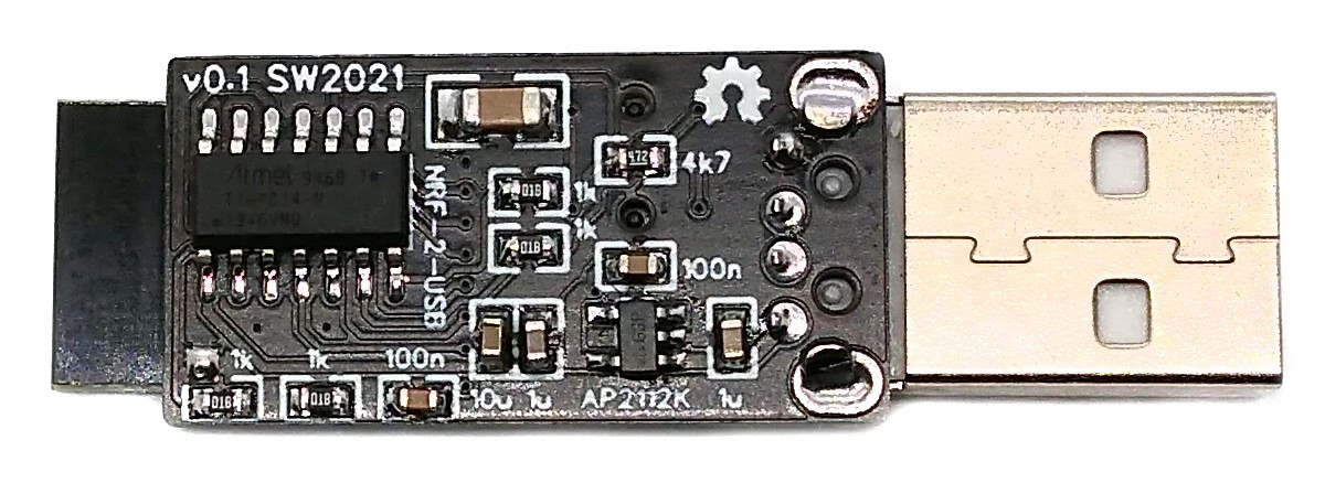
# Hardware
The wiring is pretty simple:
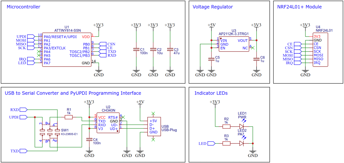
The CH330N can be replaced by a CH340N. With the toggle switch the user can select UART mode for data transfer or UPDI mode for programming the device.
# Software
## UART Implementation
The new tinyAVR are equipped with a hardware module for UART, so implementation is very easy. The internal oscillator is sufficiently accurate. The optional calibration with regard to the supply voltage was use here, although it is probably unnecessary. The receive routine is interrupt-driven and uses a simple ring buffer. For more information on the USART module refer to [Microchip Technical Brief TB3216](https://ww1.microchip.com/downloads/en/Appnotes/TB3216-Getting-Started-with-USART-DS90003216.pdf).
```c
// UART definitions and macros
#define UART_BAUD 230400 // UART baud rate (max 1/8 of F_CPU)
#define UART_BAUD_RATE 8.0 * F_CPU / UART_BAUD + 0.5
#define UART_ready() (USART0.STATUS & USART_DREIF_bm)
#define UART_available() (UART_RX_head != UART_RX_tail)
// UART RX buffer and pointer
#define UART_BUF_LEN 64 // UART RX buffer length (must be a power of two, max 256)
volatile uint8_t UART_RX_buf[UART_BUF_LEN]; // RX ring buffer
volatile uint8_t UART_RX_head = 0; // RX buffer pointer for writing
uint8_t UART_RX_tail = 0; // RX buffer pointer for reading
// UART init
void UART_init(void) {
pinOutput(PIN_TXD); // set TXD pin to output
int8_t sigrow_val = SIGROW_OSC20ERR5V; // get calibration value
int32_t baud_setting = UART_BAUD_RATE; // calculate baud register value ...
baud_setting *= (1024 + sigrow_val); // ... with error compensation ...
baud_setting /= 1024; // ... for 5V and 20MHz oscillator
USART0.BAUD = (uint16_t)baud_setting; // set BAUD
USART0.CTRLA = USART_RXCIE_bm; // enable RX interrupt
USART0.CTRLB = USART_RXEN_bm // enable RX
| USART_TXEN_bm // enable TX
| USART_RXMODE_CLK2X_gc; // double speed
}
// UART transmit data byte
void UART_write(uint8_t data) {
while(!UART_ready()); // wait until ready for next data
USART0.TXDATAL = data; // send data byte
}
// UART read data byte from RX buffer
uint8_t UART_read(void) {
while(!UART_available()); // wait for data to be received
UART_RX_tail &= (UART_BUF_LEN - 1); // limit pointer
return UART_RX_buf[UART_RX_tail++]; // read and return data byte
}
// UART RXC interrupt service routine
ISR(USART0_RXC_vect) {
UART_RX_head &= (UART_BUF_LEN - 1); // limit pointer
UART_RX_buf[UART_RX_head++] = USART0.RXDATAL; // write received byte to buffer
}
```
## SPI Implementation
The nRF24L01+ module is controlled via SPI (Serial Peripheral Interface). Since the new ATtinys also have a hardware module for this, implementation is a piece of cake. The maximum speed (half the MCU clock) is used here. For more information on the SPI module refer to [Microchip Technical Brief TB3215](https://www.microchip.com/content/dam/mchp/documents/MCU08/ApplicationNotes/ApplicationNotes/TB3215-Getting-Started-with-SPI-DS90003215.pdf).
```c
// SPI init
void SPI_init(void) {
pinOutput(PIN_MOSI); // set MOSI pin as output
pinOutput(PIN_SCK); // set SCK pin as output
SPI0.CTRLA = SPI_CLK2X_bm // double speed
| SPI_ENABLE_bm // enable SPI
| SPI_MASTER_bm // master mode
| SPI_PRESC_DIV4_gc; // prescaler 4
SPI0.CTRLB = SPI_SSD_bm; // disable SS line
}
// SPI transmit and receive a byte
uint8_t SPI_transfer(uint8_t data) {
SPI0.DATA = data; // start exchanging data byte
while(~SPI0.INTFLAGS & SPI_IF_bm); // wait for transfer to complete
return SPI0.DATA; // return received byte
}
```
## nRF24L01+ Implementation
The nRF25L01+ module is controlled by writing and reading its registers via SPI. The corresponding registers, commands and the state diagram can be found in the [datasheet](https://www.sparkfun.com/datasheets/Components/SMD/nRF24L01Pluss_Preliminary_Product_Specification_v1_0.pdf). The important functions are shown below:
```c
// NRF registers
#define NRF_REG_CONFIG 0x00 // configuration register
#define NRF_REG_RF_CH 0x05 // RF frequency channel
#define NRF_REG_RF_SETUP 0x06 // RF setup register
#define NRF_REG_STATUS 0x07 // status register
#define NRF_REG_RX_ADDR_P0 0x0A // RX address pipe 0
#define NRF_REG_RX_ADDR_P1 0x0B // RX address pipe 1
#define NRF_REG_TX_ADDR 0x10 // TX address
#define NRF_REG_FIFO_STATUS 0x17 // FIFO status register
#define NRF_REG_DYNPD 0x1C // enable dynamic payload length
#define NRF_REG_FEATURE 0x1D // feature
// NRF commands
#define NRF_CMD_R_RX_PL_WID 0x60 // read RX payload length
#define NRF_CMD_R_RX_PAYLOAD 0x61 // read RX payload
#define NRF_CMD_W_TX_PAYLOAD 0xA0 // write TX payload
#define NRF_CMD_FLUSH_TX 0xE1 // flush TX FIFO
#define NRF_CMD_FLUSH_RX 0xE2 // flush RX FIFO
// NRF global variables
uint8_t NRF_channel = 0x02; // channel (0x00 - 0x7F)
uint8_t NRF_speed = 0; // 0:250kbps, 1:1Mbps, 2:2Mbps
uint8_t NRF_tx_buffer[NRF_PAYLOAD]; // transmit buffer
uint8_t NRF_tx_addr[] = {0xE7, 0xE7, 0xE7, 0xE7, 0xE7};
uint8_t NRF_rx_addr[] = {0xC2, 0xC2, 0xC2, 0xC2, 0xC2};
const uint8_t NRF_SETUP[] = {0x26, 0x06, 0x0E};
const uint8_t* NRF_STR[] = {"250k", "1M", "2M"};
// NRF switch to Power Down
void NRF_powerDown(void) {
pinLow(PIN_CE); // return to Standby-I
NRF_writeRegister(NRF_REG_CONFIG, NRF_CONFIG | 0x00); // !PWR_UP
}
// NRF switch to RX mode
void NRF_powerRX(void) {
pinLow(PIN_CE); // return to Standby-I
NRF_writeRegister(NRF_REG_CONFIG, NRF_CONFIG | 0x03); // PWR_UP + PRIM_RX
pinHigh(PIN_CE); // switch to RX Mode
}
// NRF switch to TX mode
void NRF_powerTX(void) {
pinLow(PIN_CE); // return to Standby-I
NRF_writeRegister(NRF_REG_CONFIG, NRF_CONFIG | 0x02); // PWR_UP + !PRIM_RX
pinHigh(PIN_CE); // switch to TX Mode
}
// NRF configure
void NRF_configure(void) {
pinLow(PIN_CE); // leave active mode
NRF_writeBuffer(NRF_REG_RX_ADDR_P1, NRF_rx_addr, 5); // set RX address
NRF_writeBuffer(NRF_REG_TX_ADDR, NRF_tx_addr, 5); // set TX address
NRF_writeBuffer(NRF_REG_RX_ADDR_P0, NRF_tx_addr, 5); // set TX address for auto-ACK
NRF_writeRegister(NRF_REG_RF_CH, NRF_channel); // set channel
NRF_writeRegister(NRF_REG_RF_SETUP, NRF_SETUP[NRF_speed]); // set speed and power
NRF_writeRegister(NRF_REG_FEATURE, 0x04); // enable dynamic payload length
NRF_writeRegister(NRF_REG_DYNPD, 0x3F); // enable dynamic payload length
NRF_writeCommand(NRF_CMD_FLUSH_RX); // flush RX FIFO
NRF_powerRX(); // switch to RX Mode
}
// Check if data is available for reading
uint8_t NRF_available(void) {
if(NRF_readRegister(NRF_REG_STATUS) & 0x40) return 1;
return(!(NRF_readRegister(NRF_REG_FIFO_STATUS) & 0x01));
}
// Read payload bytes and send them via UART
void NRF_to_UART(void) {
uint8_t len = NRF_readRegister(NRF_CMD_R_RX_PL_WID); // read payload length
pinLow(PIN_CSN); // start SPI transfer
SPI_transfer(NRF_CMD_R_RX_PAYLOAD); // read payload command
while(len--) UART_write(SPI_transfer(0)); // transfer payload to UART
pinHigh(PIN_CSN); // stop SPI transfer
NRF_writeRegister(NRF_REG_STATUS, 0x40); // clear status flags
}
// Send a data package (max length 32)
void NRF_send(uint8_t *data, uint8_t len) {
NRF_writeRegister(NRF_REG_STATUS, 0x30); // clear status flags
NRF_writeCommand(NRF_CMD_FLUSH_TX); // flush TX FIFO
NRF_writeBuffer(NRF_CMD_W_TX_PAYLOAD, data, len); // write payload
NRF_powerTX(); // switch to TX Mode; transmit
while(!(NRF_readRegister(NRF_REG_STATUS) & 0x30)); // wait until finished
NRF_powerRX(); // return to listening
}
```
## Main Function
The main function brings it all together:
```c
int main(void) {
// Setup MCU
_PROTECTED_WRITE(CLKCTRL.MCLKCTRLB, 1); // set clock frequency to 10 MHz
// Setup
uint8_t tx_ptr = 0; // NRF TX buffer pointer
pinOutput(PIN_LED); // set LED pin as output
EEPROM_get(); // read user settings from EEPROM
NRF_init(); // setup NRF
SPI_init(); // setup SPI serial interface
UART_init(); // setup UART serial interface
NRF_configure(); // configure NRF
sei();
// Loop
while(1) {
if(NRF_available()) { // something coming in via NRF?
pinHigh(PIN_LED); // switch on LED
NRF_to_UART(); // send received payload via UART
}
if(UART_available()) { // something coming in via UART?
uint8_t c = UART_read(); // read the character ...
NRF_tx_buffer[tx_ptr++] = c; // ... and write it to the buffer
if((tx_ptr == NRF_PAYLOAD) || (c == '\n')) { // buffer full or new line?
if(NRF_tx_buffer[0] == CMD_IDENT) parse(); // is it a command? -> parse
else { // not a command?
pinHigh(PIN_LED); // switch on LED
NRF_send(NRF_tx_buffer, tx_ptr); // send the buffer via NRF
}
tx_ptr = 0; // reset buffer pointer
}
}
pinLow(PIN_LED); // switch off LED
}
}
```
## Compiling and Uploading
- Set the selector switch on the device to UPDI.
- Plug the device into a USB port of your PC.
### If using the Arduino IDE
- Open your Arduino IDE.
- Make sure you have installed [megaTinyCore](https://github.com/SpenceKonde/megaTinyCore).
- Go to **Tools -> Board -> megaTinyCore** and select **ATtiny1614/1604/814/804/414/404/214/204**.
- Go to **Tools** and choose the following board options:
- **Chip:** Any chip should work
- **Clock:** 10 MHz internal
- **Programmer:** SerialUPDI (230400 BAUD)
- Leave the rest at the default settings.
- Go to **Tools -> Burn Bootloader** to burn the fuses.
- Open USB2NRF sketch and click **Upload**.
- Set the selector switch on the device back to UART.
### If using the makefile (Linux/Mac)
- Download [AVR 8-bit Toolchain](https://www.microchip.com/mplab/avr-support/avr-and-arm-toolchains-c-compilers) and extract the sub-folders (avr, bin, include, ...) to /software/tools/avr-gcc. To do this, you have to register for free with Microchip on the download site.
- Open a terminal.
- Navigate to the folder with the makefile and the Arduino sketch.
- Run "make install" to compile, burn the fuses and upload the firmware.
- Set the selector switch on the device back to UART.
# Operating Instructions
Set the selector switch on the device to UART. Plug the device into a USB port of your PC. Open a serial monitor and set it to 230400 BAUD.
Enter the text to be sent, terminated with a Newline (NL or '\ n'). A string that begins with an exclamation mark ('!') is recognized as a command. The command is given by the letter following the exclamation mark. Command arguments are appended as bytes in 2-digit hexadecimal directly after the command. The following commands can be used to set the NRF:
|Command|Description|Example|Example Description|
|-|:-|:-|:-|
|c|set channel|!c2A|set channel to 0x2A (0x00 - 0x7F)|
|t|set TX address|!t7B271F1F1F|addresses are 5 bytes, LSB first|
|r|set RX address|!t41C355AA55|addresses are 5 bytes, LSB first|
|s|set speed|!s02|data rate (00:250kbps, 01:1Mbps, 02:2Mbps)|
Enter just the exclamation mark ('!') for the actual NRF settings to be printed in the serial monitor. The selected settings are saved in the EEPROM and are retained even after a restart.
# References, Links and Notes
1. [ATtiny814 Datasheet](https://ww1.microchip.com/downloads/en/DeviceDoc/ATtiny417-814-816-817-DataSheet-DS40002288A.pdf)
2. [nRF24L01+ Datasheet](https://www.sparkfun.com/datasheets/Components/SMD/nRF24L01Pluss_Preliminary_Product_Specification_v1_0.pdf)
3. [Microchip Technical Brief TB3215](https://www.microchip.com/content/dam/mchp/documents/MCU08/ApplicationNotes/ApplicationNotes/TB3215-Getting-Started-with-SPI-DS90003215.pdf)
4. [Microchip Technical Brief TB3216](https://ww1.microchip.com/downloads/en/Appnotes/TB3216-Getting-Started-with-USART-DS90003216.pdf)
# License

This work is licensed under Creative Commons Attribution-ShareAlike 3.0 Unported License.
(http://creativecommons.org/licenses/by-sa/3.0/)
Design Drawing
schematic diagram
(
1
/
)
PCB
(
1
/
)
The preview image was not generated, please save it again in the
editor.
| ID | Name | Designator | Footprint | Quantity | BOM_Manufacturer Part | BOM_Supplier | BOM_Manufacturer |
|---|---|---|---|---|---|---|---|
| 1 | 100n | C1,C4 | 0603 | 2 | CC0603KRX7R9BB104 | LCSC | YAGEO |
| 2 | 10u | C2 | 0603 | 1 | CL10A106MA8NRNC | LCSC | SAMSUNG |
| 3 | 47u | C3 | 1206 | 1 | 1206F476M160NT | LCSC | FH |
| 4 | 1u | C5,C6 | 0603 | 2 | CL10A105KB8NNNC | LCSC | SAMSUNG |
| 5 | PWR | LED1 | LED_0603 | 1 | 19-217/GHC-YR1S2/3T | LCSC | EVERLIGHT |
| 6 | PA7 | LED2 | LED_0603 | 1 | KT-0603R | LCSC | KENTO |
| 7 | 1k | R1,R2,R3 | 0603 | 3 | 0603WAF1001T5E | LCSC | UNI-ROYAL(厚声) |
| 8 | K3-2380S-E1 | SW1 | SW-SMD_K3-2380S-E1 | 1 | K3-2380S-E1 | LCSC | Rectangular Connectors - Contacts |
| 9 | ATTINY814-SSN | U1 | SOIC-14_150MIL | 1 | ATTINY814-SSNR | LCSC | Microchip Tech |
| 10 | CH340N | U2 | SOP-8_150MIL | 1 | CH340N | LCSC | WCH(南京沁恒) |
| 11 | AP2112K-3.3TRG1 | U3 | SOT-25-5 | 1 | AP2112K-3.3TRG1 | LCSC | DIODES |
| 12 | NRF24L01 | U4 | NRF24L01+SMD | 1 | mininrf24l01 | aliexpress | Greatwall |
| 13 | USB-Plug | USB | USB-M-48 | 1 | USB-05 | LCSC | SOFNG |
Unfold
Project Members


 5
5
 7
7
Collect to album
Target complaint
Related Projects
Change a batch
Loading...
Add to album
×
Loading...
reminder
×
Do you need to add this project to the album?