


© 2024 EasyEDA Some rights reserved ISO/IEC
Editor Version
×
Standard

1.Easy to use and quick to get started
2.The process supports design scales of 300 devices or 1000 pads
3.Supports simple circuit simulation
4.For students, teachers, creators
Profession

1.Brand new interactions and interfaces
2.Smooth support for design sizes of over 5,000 devices or 10,000 pads
3.More rigorous design constraints, more standardized processes
4.For enterprises, more professional users
Ongoing
STD W5200 Ethernet Shield
Mode: Editors' pick
- 4
Update time:
2021-04-10 10:08:21
Creation time:
2016-01-07 12:13:01
Description
## ETHERNET INTERFACE BRICK AND SHIELD ##
Your Ethernet Shield gets a total renewal now! This shield provides you instant Internet connectivity with a high spec Ethernet controller, W5200, with twice the buffer size of v1.0 and support for up to eight simultaneous TCP/UDP connections. An included SD slot enables applications that require storing large amounts of data, like IoT data logging. Thanks to a lowered RJ45 pot, you can flexibly add most of shields on top of this Ethernet Shield.
![Ethernet Shield V2.0][1]
Features:
High speed Ethernet controller W5200
SPI interface
32 Kbytes inner buffer
Minimal RJ45 Ethernet port
Support up to eight simultaneous TCP/UDP connections
Handy SD card function
Grove ports for I2C and UART preformed
![Interface][2]
Hardware Configuration
RJ45: Ethernet Port;
IC HX1198: 10/100BASE-T signal port;
IC W5200: a hardwired TCP/IP Ethernet Controller;
U3: IC CJ117, low dropout linear regulator;
U6: IC 74VHC125PW, quad buffer;
Reset KEY: Reset Ethernet shield and Arduino when pressed;
SD card: support Micro SD card in FAT16 or FAT32; maximum storage is 2GB.
Pins usage on Arduino
D4: SD card chip select
D10: W5200 Chip Select
D11: SPI MOSI
D12: SPI MISO
D13: SPI SCK
Notice:
Both W5200 and SD card communicate with Arduino via SPI bus. Pin 10 and pin 4 are chip select pins for W5200 and SD slot. They cannot be used as general I/O.
Usage
We are going to build a simple web server that answer request from a client and store the readings from A0 through A5 to SD card.
Step 1: Hookup
1. Mount Ethernet Shield v2.0 to your Arduino;
2. Connect the shield to your computer or a network hub or a router with a standard Ethernet cable;
3. Connect Arduino to PC via USB cable;
4. Insert an SD card to the SD card slot.
![500px-IMG_0039][3]
Step 2: Upload the program
1. Download the library:https://github.com/Seeed-Studio/Ethernet_Shield_W5200 Note: Depreciated/Old Library for 1.0.x IDE: Link.
2. Unzip and put it in the libraries file of Arduino IDE by the path: ..\arduino-1.0.1\libraries.
3. Restart the Arduino IDE.
4. Open the example "WebServerWithSD" via the path: File --> Examples --> EthernetV2.0 --> WebServerWithSD. This example shows you how to build up a simple web server that displays the readings of anolog A0 through A5 when requested. After that, store those readings into SD card.
Note:
This new library covers all functions included in the build-in Ethernet library of Arduino IDE. You can use other examples in the same way as that in the preceding Ethernet library.
5. Upload the program to Arduino. If you do not know how to upload code, please click here.
![Open_WebSeverWithSD_code][4]
In this code ,we have defined pin 4 as SD card chip select port and pin 10 as W5200 chip select port.
Firstly, it will send a link to this client if there is a client requesting access to this server.Then send the value of each analog input pin to the network.
Finally you can view each analog pin by opening SD Card file.
Step 3: Results
Open a web browser and enter the IP address of your controller. It's dependent on your local network but used to be 192.168.168.178. Then you should find the readings of A0 through A5 popping up as shown below.
![Ethernet_Score][5]
To check what's going on to the SD card, open the serial monitor. You can use the built-in serial monitor of Arduino IDE or a serial monitor tool as us. After opening a serial monitor, you can read the content of file "test.txt" which we created to store the readings of analog pins.
![WebServerWithSD_Result][6]
Notice:
1) Make sure the Ethernet Shield and your computer are in the same local network.
2) Once the code has been successfully uploaded, it's fine to disconnect the board from your computer and apply independent power to it, leaving it run alone.
[1]: /editor/20160107/568e797d99732.jpg
[2]: /editor/20160107/568e79dad7d9a.jpg
[3]: /editor/20160107/568e7a3793ee0.jpg
[4]: /editor/20160107/568e7a756e141.jpg
[5]: /editor/20160107/568e7aef6ea99.jpg
[6]: /editor/20160107/568e7b23a4546.jpg
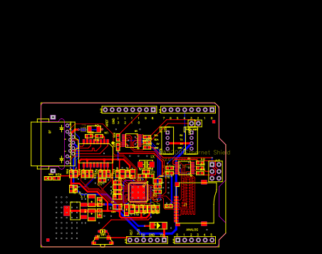
Design Drawing
schematic diagram
(
1
/
)
PCB
(
1
/
)
The preview image was not generated, please save it again in the
editor.
| ID | Name | Designator | Footprint | Quantity |
|---|---|---|---|---|
| 1 | GREEN | PWR | LED-0603 | 1 |
| 2 | R* | R28 | R0603 | 1 |
| 3 | PAD-MARK | P3,P2 | ROUND-MARK-1.0 | 2 |
| 4 | 1uF | C24,C23,C22,C21,C20,C19 | C0805 | 6 |
| 5 | 10V_22uF | C16,C13 | AVX-B | 2 |
| 6 | 3.3k | R27,R15,R13,R12,R11 | R0603 | 5 |
| 7 | DNP | PWDN,W!INT | 1P-6535MIL | 2 |
| 8 | 1k | R25,R24,R18,R10,R17,R16 | R0603 | 6 |
| 9 | 100nF | C12,C10,C9,C8,C5,C11,C1,C17,C15 | C0603 | 9 |
| 10 | 74VHC125PW | U6,U2 | TSSOP14 | 2 |
| 11 | 1N4148WS | D3 | SOD323 | 1 |
| 12 | BUTTON_4P_SMD | SW1 | 4P-SMD-7X3.5X3.5 | 1 |
| 13 | 10V_10uF | C7 | AVX-A | 1 |
| 14 | RED | D2 | LED-0603 | 1 |
| 15 | 10K | R9,R8,R7,R6,R5,R4,R2 | R0603 | 7 |
| 16 | 47k | R3 | R0603 | 1 |
| 17 | 8.2pF | C3,C2 | C0603 | 2 |
| 18 | 1M | R1 | R0603 | 1 |
| 19 | 25MHz | X1 | 2P-SMD-5X3.2 | 1 |
| 20 | 28.7K1% | R14 | R0603 | 1 |
| 21 | 10uF | C6,C18,C14 | C0805 | 3 |
| 22 | W5200 | U5 | QFN48 | 1 |
| 23 | CJ1117-3.3 | U3 | SOT-223 | 1 |
| 24 | 49.9_1% | R23,R22,R21,R20 | R0603 | 4 |
| 25 | DNP | P1 | 2P-SMD-1.78X1.27 | 1 |
| 26 | M7 | D1 | D2010 | 1 |
| 27 | RJ45-MJ88-BX11-RVSL2 | J8 | RJ45-MJ88-BX11-RVSL2 | 1 |
| 28 | 1000v_1nF | C4 | C1206 | 1 |
| 29 | 75 | R26,R19 | R0603 | 2 |
| 30 | HX1198NL | U4 | SOIC16-9.53 | 1 |
| 31 | TWIG-4P-2.0 | I2C,UART | 4P-2.0 | 2 |
| 32 | SD card holder | J1 | 9P-SMD-W-RING | 1 |
| 33 | ARDUINO | U1 | ARDUINO | 1 |
Unfold
Project Members


 0
0
 4
4
Collect to album
Target complaint
Related Projects
Change a batch
Loading...
Add to album
×
Loading...
reminder
×
Do you need to add this project to the album?