

 Ongoing
SparkFun UDB5 - PIC UAV Development Board
STDSparkFun UDB5 - PIC UAV Development Board
License
:Description


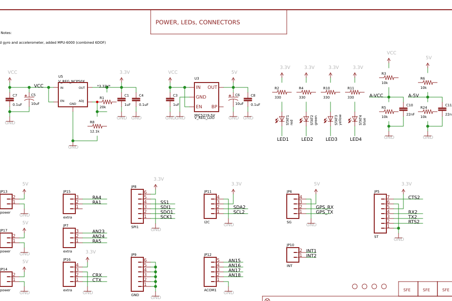
Description: Our UAV Development Board is back! The UDB5 (UAV Development Board version 5) comes populated with a dsPIC33FJ256 CPU, and the impressive MPU-6000, a MEMS 3-axis gyroscope and 3-axis accelerometer. The on-board Invensense gyro even has enough vibration tolerance to be used in RC heli applications.
By itself, the board can be used to develop a three axis IMU controller. By addition of an EM406 or D2523T GPS receiver, it can be used to develop a UAV controller for an RC car, plane, helicopter, or boat. It comes with self-testing firmware that can serve as a starting point for you to develop your own control and navigation firmware. There is even fully functional, open source autopilot firmware available. We’ve made a few changes with the UDB5, we’ve removed the MMA7361 three axis accelerometer, the dual axis IDG500 gyro, and the single axis ISZ500 gyro and moved to an MPU-6000. The PCB form factor hasn’t changed. If you like, you can add a reset button and/or a 0.2F super cap.
Note: For programming, we recommend the PICkit3. Check the related products below.
Note: A GPS module is not included. Check the related products below.
Features:
compatible with 20-channel EM-406A SiRF III GPS
compatible with 48-channel EM-506 GPS with SiRF Star IV chipset
compatible with 50-channel GS407 Helical GPS
dsPIC33FJ256GP710A Controller (with onboard 3.3V and 5V glue logic)
dsPIC runs at 80MHz (40 MIPS) with 8MHz resonator and PLL
MPU-6000 MEMS 3-axis gyroscope and 3-axis accelerometer
External 256Kbit EEPROM
Up to 8 Input, 8 output PWM points
6-wire debug header or ICSP header
4 separate colored status LEDs
On board 3.3V and 5V regulators (150mA max)
Spare USART connection for debugging, flight logging, wireless telemetry, etc.
I/O pins include a CAN, an I2C, and a SPI port
30 spare analog and digital I/O pins for debugging and interfacing to sensors
For more detail and Documents, Please visit: http://www.sparkfun.com/products/11703


BOM
 Clone
CloneProject Members
 Empty
Empty
Comment