

 Ongoing
Reflecting a secondary impedance to the primary
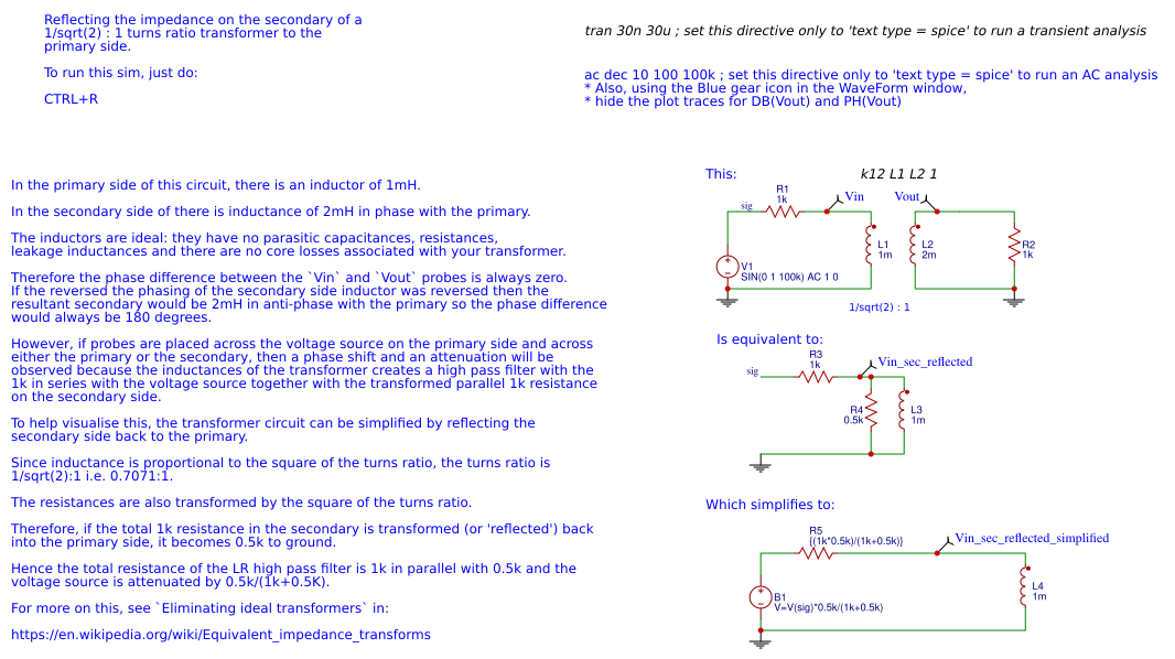
STDReflecting a secondary impedance to the primary
2.7k
0
0
0
Mode:Full
License
:Public Domain
Creation time:2016-01-31 01:02:05Update time:2021-04-11 13:53:56
Description
Design Drawing
BOM
 Clone
CloneAdd to Album
0
0
Share
Report
Project Members
Followers0|Likes0
Related projects
 Empty
Empty
Comment