

 Ongoing
Micro Bridge + UPDI
STDMicro Bridge + UPDI
1.4k
0
0
0
Mode:Full
License
:Public Domain
Creation time:2020-09-18 20:45:39Update time:2021-02-06 19:32:57
Description
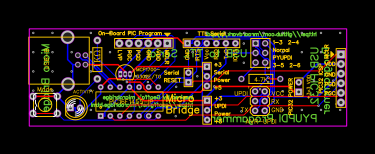
Geoff’s Micro Bridge + UPDI#
USB to Serial Bridge and USB PIC32 Programmer and UPDI Programmer
CAUTION! UNTESTED – WORK IN PROGRESS – UNDER CONSTRUCTION
FEB 2021 jlcpcb Order - awaiting arrivial
The Microbridge + UPDI has three operating modes:
- USB to Serial converter mode using the TTLSerial interface.
- PIC32 programming mode using the PIC32 ICSP interface.
- UPDI programming mode using the AVR-UPDI interface.
The Mode switch is used to change to PIC32 mode and the LED is used to indicate the current operating mode and serial transmit/receive activity.
USB to Serial Converter Mode
On power up the Microbridge will default to running as a USB to Serial converter.  In this mode it appears as a serial over USB port on your desktop or laptop computer and transfers the data as a TTL serial stream to the Micromite. When you run a terminal emulator on your PC you can then access a serial device (console) via USB and the Microbridge.

UPDI Mode
This is PY-UPDI, it uses PYUPDI to program the NEW AVR chips that use UPDI as there ISP.
https://github.com/mraardvark/pyupdi

Windows 10 includes the required device driver for the Microbridge.
For other operating systems you can download the driver. (See Attachments)
The Microbridge emulates the Microchip MCP2200 so you can also download drivers from that website.
https://www.microchip.com/wwwproducts/en/MCP2200

With the correct device driver installed the Microbridge will appear as a serial port to your computer. For example, in Windows it is represented by a COM port number which you can find by checking Device Manager -> Ports (COM & LPT) as shown on the right.  Using a terminal emulator such as Tera Term you can connect to this virtual serial port and anything typed on your computer's keyboard will be sent via the serial interface of the Microbridge and anything received on this interface will be sent to your terminal emulator's screen.  To aid in fault finding the LED on the Microbridge will flash for every character sent or received.

Within your terminal emulator's setup you can set the baud rate for the serial interface and the Microbridge will automatically adopt this speed on its serial interface.

If you jumper the Serial Reset 2 pin header on the Microbridge, you can also use the Microbridge to send a reset, on FTDI pin 2, to the serial device (if is supports it). This is done by sending a serial break signal to the Microbridge. In Tera Term this is done by pressing the ALT-B keys.
Another method of generating a reset is to press and hold the MODE switch on the Microbridge for two or more seconds, its LED will flash and the RESET pin will be pulsed low.

FYI
This board does NOT support handshacking!
It is TX / RX only
PIC32 Programmer Mode
As a PIC32 programmer the Microbridge uses the same pinouts as the Microchip PICkit 3 programmer and can be plugged into the same six pin programming socket.

To use the Microbridge as a programmer you should momentarily press the MODE switch on the Microbridge - the Microbridge will immediately switch to its PIC32 programming mode and the on-board LED will illuminate to confirm this.  If you did not intend to enter programming mode you can revert to the USB/Serial mode by pressing and holding the mode switch for two seconds or more.

To program a chip you use the Windows program pic32prog.exe (available at the bottom of this page).  There are versions for macOS and Linux also available on the Internet.  The Windows version does not need installation so you can just copy the executable to a convenient location and start a DOS box in that folder. The command line used to program a PIC32 chip is as follows:

pic32prog -d ascii:comxx yyyy.hex

where xx is the COM port number and yyyy is the name of the firmware file.
The COM port number is the same as that allocated by Windows when the Microbridge was in its USB to Serial converter mode.

For example, if your Microbridge was allocated the virtual serial port of COM6 and the file that you wanted to program was "m.hex", the command line that you should use is:

pic32prog -d ascii:com6 m.hex

When you press enter at the end of this command line pic32prog will upload the hex file to the Microbridge, program it into the PIC32 then read back the programmed data to verify that the programming operation was executed correctly.

At the completion of the programming operation the LED will turn off and the Microbridge will revert to operating as a USB to Serial converter.
Power Supply
The Microbridge has its own 3.3V regulator which it can supply up to 150mA
This voltage can be made available on the serial interface connector by installing a jumper the +3v3 to the center of the Serial VCC 3 pin header.

The USB 5V supply can also be made available on this connector - its current rating is determined by your computer's capability.
This voltage can be made available on the serial interface connector by installing a jumper the +5 to the center of the Serial VCC 3 pin header.
Credits

Geoff’s Projects https://geoffg.net/microbridge.html

The Microbridge is the creation of a number of brilliant people working together:

1. Peter Mather in the UK wrote the Microbridge firmware for the PIC16F1455
2. Serge Vakulenko in California wrote pic32prog
3. Robert Rozee in New Zealand wrote the ASCII ICSP interface for pic32prog
4. MicroBlocks (a company in Thailand) developed the original idea but did not publish their code

PYUPDI https://github.com/mraardvark/pyupdi
BY mraardvark
Design Drawing
schematic diagram

Preview
Micro-Bridge-UPDIOpen in Editor
PCB

Preview
Micro-Bridge-UPDIOpen in Editor
BOM
| ID | Name | Designator | Footprint | Quantity |
|---|---|---|---|---|
| 1 | PIC32 POWER | 1X2PIN | 1X2PIN | 1 |
| 2 | Serial RESET | 1X1PIN | 1X2PIN | 1 |
| 3 | USB-B | U3 | USBB-1J_ | 1 |
| 4 | PIC16F1455-IP | U1 | DIP14 | 1 |
| 5 | ACTIVITY | LED1 | LED-5MM | 1 |
 Clone
CloneAdd to Album
0
0
Share
Report
Project Members
Followers0|Likes0
Related projects
 Empty
Empty
Comment