

 Ongoing
ATtiny84 TinyICOC
STDATtiny84 TinyICOC
License
:CC-BY-SA 3.0
Description
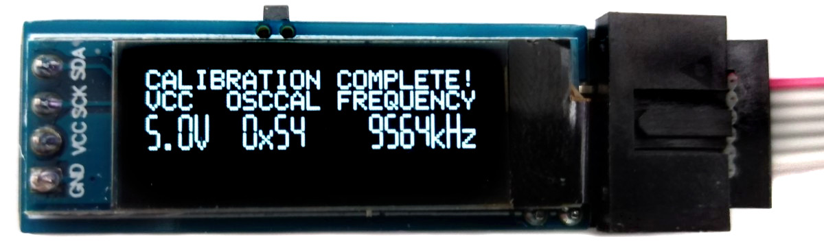
TinyICOC - AVR In-Circuit Oscillator Calibrator
Sometimes AVRs are operated without an external clock. The internal oscillator does a good job in most applications, but when it comes to precise timing, its +/-10% accuracy is often insufficient. Fortunately, the oscillator can be calibrated, increasing its accuracy to +/-2% or better. There are a few ways to perform this manual calibration, but several steps are required. The TinyICOC does this fully automatically. Simply connect the device to the target MCU via the ICSP header and press the button.
- Project Video (YouTube): https://youtu.be/0rUVBRZE3q4
- Firmware (Github): https://github.com/wagiminator/ATtiny84-TinyICOC
Hardware
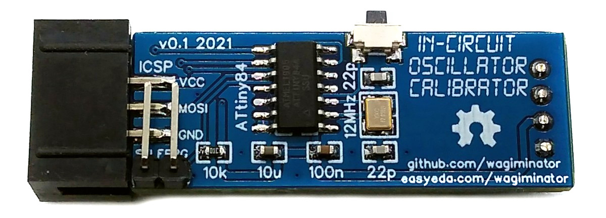
The TinyICOC is powered by the target board through the ICSP connection. On the one hand, this means that there is no need for a separate power supply and, on the other hand, the oscillator of the target MCU is automatically calibrated at the supply voltage of the target board.
The ATtiny84 was chosen as the microcontroller for the TinyICOC because it has exactly the necessary number of GPIO pins. For accurate frequency measurements, the ATtiny84 is operated with an external 12 MHz crystal. Since the current software version only requires around 3 KBytes, an ATtiny44 can also be used.
The user interface utilizes one button and a 128x32 pixels OLED display.
Software
Basic Principle
To carry out the calibration, a program is first uploaded to the target MCU using the integrated In-Circuit Serial Programmer (ICSP). This program applies an oscillating signal with half the clock frequency to the MOSI pin of the target MCU. Since the fuses were previously set so that the target MCU clock runs with a prescaler of 8, a signal with 1/16 of the oscillator frequency is applied to that pin. This frequency is measured by the timers of the ATtiny84 and compared with the target value. The oscillator calibration value (OSCCAL) is then adjusted accordingly and written into the EEPROM of the target MCU. This value is in turn read by the target MCU and written to its OSCCAL register. This process is repeated until the OSCCAL value, which leads to the lowest frequency deviation, has been found.
The current firmware version supports the following MCUs:
| MCU | OSC Frequency |
|---|---|
| ATtiny13 (A) | 9.6 MHz |
| ATtiny24/44/84 (A) | 8 MHz |
| ATtiny25/45/85 | 8 MHz |
| ATmega8 (A) | 8 MHz |
In-Circuit Serial Programmer
The code for the In-Circuit Serial Programmer (ICSP) is quite unspectacular. Simply put, for each action, a series of instructions are sent over the data lines to the target MCU and the corresponding response is read. The process and the instructions are well described in the data sheet.
Frequency Measurement
The timer/counters of the ATtiny84 are used for the frequency measurement. The MOSI pin of the target MCU, which outputs a signal with 1/16 of its oscillator frequency, is connected to the T0 input of the ATtiny84. Timer0 counts the pulses at T0 and timer1 stops the measurement after a time of 32 milliseconds. From this, the oscillator frequency of the target MCU can finally be calculated.
I²C OLED Implementation
The I²C protocol implementation is based on a crude bitbanging method. It was specifically designed for the limited resources of ATtiny10 and ATtiny13, but it works with some other AVRs (including the ATtiny84) as well. The functions for the OLED are adapted to the SSD1306 OLED module, but they can easily be modified to be used for other modules. In order to save resources, only the basic functionalities which are needed for this application are implemented. For a detailed information on the working principle of the I²C OLED implementation visit TinyOLEDdemo.
Compiling and Uploading
The same ICSP connector can be used to upload the firmware, which is otherwise intended for the connection to the target board. To do this, the SELFPRG jumper must be set before the upload. Don't forget to remove it after uploading the firmware!
If using the Arduino IDE
- Make sure you have installed ATtinyCore.
- Go to Tools -> Board -> ATtinyCore and select ATtiny24/44/84(a) (No bootloader).
- Go to Tools and choose the following board options:
- Chip: ATtiny84(a)
- Clock: 12 MHz (external)
- Millis/Micros: disabled
- Leave the rest at the default settings
- Connect your programmer to your PC and to the ICSP header of the device.
- Go to Tools -> Programmer and select your ISP programmer (e.g. USBasp).
- Go to Tools -> Burn Bootloader to burn the fuses.
- Open TinyICOC sketch and click Upload.
If using the precompiled hex-file
- Make sure you have installed avrdude.
- Connect your programmer to your PC and to the ICSP header of the device.
- Open a terminal.
- Navigate to the folder with the hex-file.
- Execute the following command (if necessary replace "usbasp" with the programmer you use):
avrdude -c usbasp -p t84 -U lfuse:w:0xff:m -U hfuse:w:0xd5:m -U efuse:w:0xff:m -U flash:w:tinyicoc.hex
If using the makefile (Linux/Mac)
- Make sure you have installed avr-gcc toolchain and avrdude.
- Connect your programmer to your PC and to the ICSP header of the device.
- Open the makefile and change the programmer if you are not using usbasp.
- Open a terminal.
- Navigate to the folder with the makefile and the Arduino sketch.
- Run "make install" to compile, burn the fuses and upload the firmware.
Operating Instructions
Warning: The firmware on the target MCU will be erased!
- Connect the TinyICOC to the ICSP header of the target board.
- Provide power to the target board.
- Push the button.
After the calibration process, the optimal OSCCAL value remains in memory address 0 of the EEPROM and can continue to be used. To do this, program the EEFUSE to preserve EEPROM memory through the chip erase cycle, otherwise the OSCCAL value will be lost after uploading new firmware. Your code should then contain the following function:
#include
void readOSCCAL(void) {
  uint8_t value = eeprom_read_byte(0);
  if (value < 0xFF) OSCCAL = value;
}
Of course, the OSCCAL value can also be set directly without the EEPROM. Remember that the OSCCAL value is displayed in hexadecimal.
OSCCAL = 0x66;
References, Links and Notes
- TinyCalibrator
- I²C OLED Tutorial
- Ralph Doncaster's PiggyFuse
- Oscillator Calibration Sketch for ATtiny13
- Oscillator Calibration Sketch for ATtiny25/45/85
- ATtiny84 Datasheet
- ATtiny85 Datasheet
- ATtiny13A Datasheet
License

This work is licensed under Creative Commons Attribution-ShareAlike 3.0 Unported License.
(http://creativecommons.org/licenses/by-sa/3.0/)


BOM
 Clone
CloneProject Members
 Empty
Empty
Comment