


© 2024 EasyEDA Some rights reserved ISO/IEC
Editor Version
×
Standard

1.Easy to use and quick to get started
2.The process supports design scales of 300 devices or 1000 pads
3.Supports simple circuit simulation
4.For students, teachers, creators
Profession

1.Brand new interactions and interfaces
2.Smooth support for design sizes of over 5,000 devices or 10,000 pads
3.More rigorous design constraints, more standardized processes
4.For enterprises, more professional users
Ongoing
STD ATtiny814 Power Analyzer
License: CC-BY-SA 3.0
Mode: Editors' pick
- 28
Update time:
2022-05-10 05:47:30
Creation time:
2020-03-14 19:14:53
Description
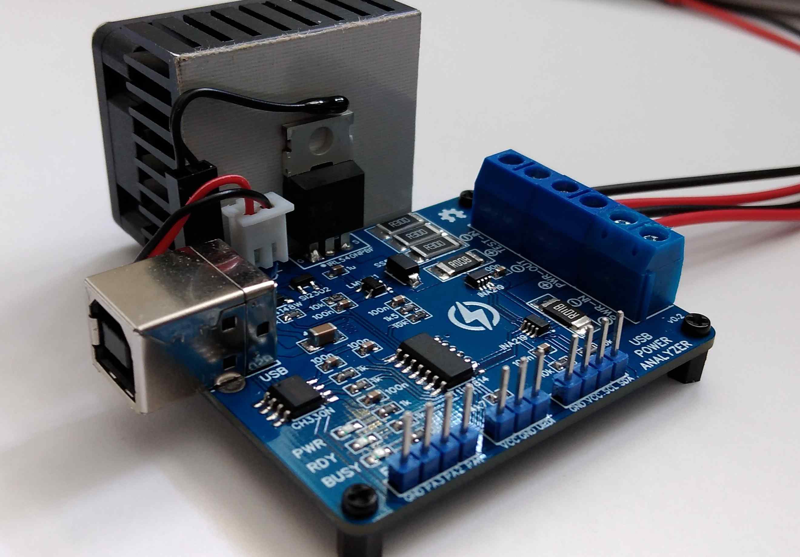
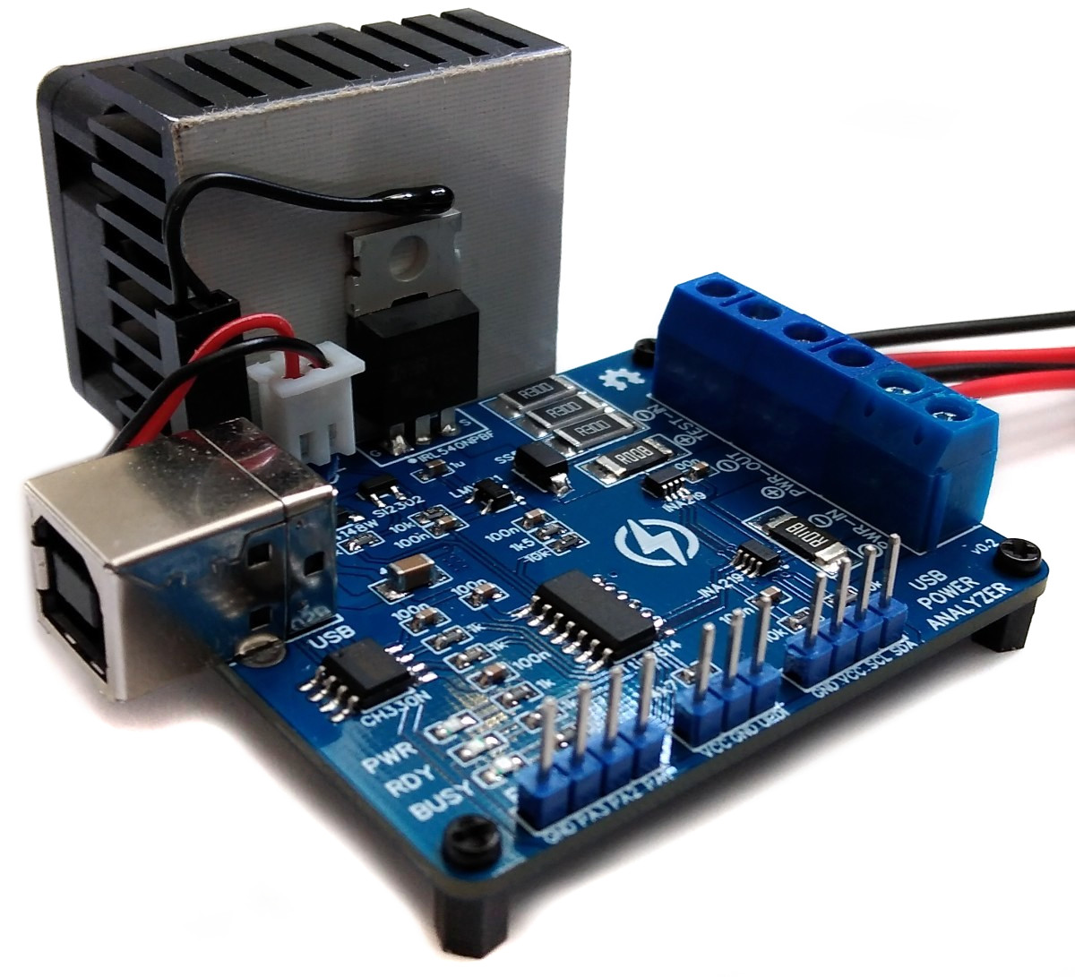
# Power Supply Analyzer with USB Interface based on ATtiny814
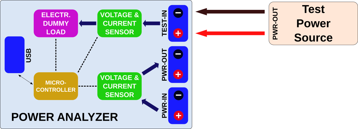
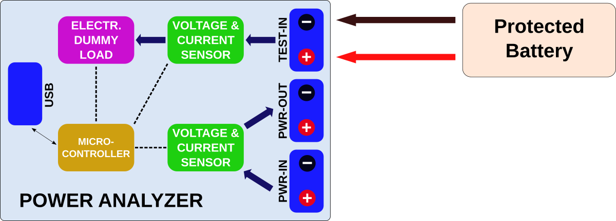
The Power Analyzer is a programmable electronic constant current dummy load with two high side voltage and current sensors for an automatic analysis of power supplys, DC/DC converters, voltage regulators, batteries, chargers, power consumers and others. The device can be controlled via USB serial interface using a serial monitor or the provided Python skripts. Data can be exported to spread sheet programs or directly be analyzed by the Python skript.
- Project Video (YouTube): https://youtu.be/q4-aywmeqHs
- Firmware (Github): https://github.com/wagiminator/ATtiny814-Power-Analyzer
# Hardware
The electronic load control circuit, which essentially consists of an operational amplifier, a MOSFET and a shunt resistor, ensures that the same current flows regardless of the voltage applied.
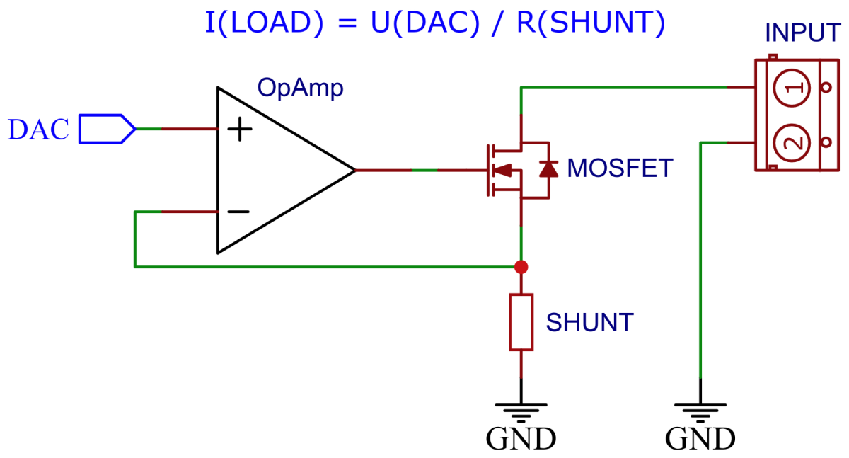
For this purpose, a 100mΩ shunt consisting of three 300mΩ resistors in parallel for proper heat dissipation is located in the load circuit, via which the current is measured. The [LMV321](https://www.onsemi.com/pdf/datasheet/lmv321-d.pdf) rail-to-rail OpAmp compares this with the target value, which is specified by the ATtiny's internal digital to analog converter (DAC) via a voltage divider and accordingly controls the gate of an [IRL540N](https://datasheet.lcsc.com/lcsc/1808281632_Infineon-Technologies-IRL540NPBF_C111607.pdf) logic level power MOSFET, which in turn adjusts the current through its internal resistance set in this way.
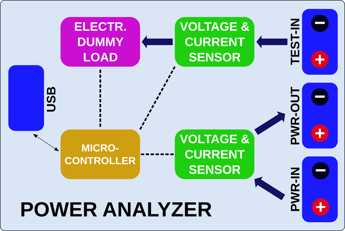
Voltage and current are measured via a high side 8mΩ shunt resistor connected to an [INA219](https://www.ti.com/lit/ds/symlink/ina219.pdf) with a resolution of 4mV/1mA. A second INA219 is connected to another 8mΩ shunt resistor between the PWR-IN and PWR-OUT terminal. The INA219 is a current shunt and power monitor with an I²C-compatible interface. The device monitors both shunt voltage drop and bus supply voltage, with programmable conversion times and filtering. A programmable calibration value, combined with an internal multiplier, enables direct readouts of current in amperes. The selected shunt resistance of 8mΩ enables both a very small influence on the circuit and a measurement with a resolution of 1mA. For an accurate measurement, a shunt resistor with a low tolerance (1% or better) should be selected.
The Power Analyzer is connected via USB to a PC or a RaspberryPi. Commands to the Analyzer can be sent via a serial monitor or by the GUI-based Python skript. The Analyzer has different built-in automatic test algorithms. The collected data is sent back via the serial interface/USB to the PC/RaspberryPi. The ATtiny814 constantly measures power and temperature of the heatsink. It controls the fan and cuts off the load when the temperature gets too hot.
# Software
## Load Control via DAC
The ATtiny814 controls the electronic dummy load with its internal digital to analog converter (DAC). All of its 5 internal reference voltages are being used in order to get the maximum accuracy and resolution of the DAC. The DAC is connected to an OpAmp which acts as a unity gain amplifier controlling the resistance of the MOSFET.
```c
// DAC reference voltages (load current = DAC voltage * R16 / (R15 + R16) / R_SHUNT)
// Reference voltages: 0.55V, 1.1V, 1.5V, 2.5V, 4.3V
const uint8_t DACREF[] = {0x00, 0x01, 0x04, 0x02, 0x03}; // CTRLA.DAC0REFSEL values
const uint16_t DACCUR[] = { 717, 1434, 1956, 3260, 5608}; // max current in mA
uint8_t DACreference = 0; // start with 0.55V reference
// Setup the digital to analog converter (DAC)
void DAC_init(void) {
VREF_CTRLB |= VREF_DAC0REFEN_bm; // enable DAC reference
_delay_us(25); // wait for Vref to start up
pinDisable(DAC_PIN); // disable digital input buffer
DAC0.CTRLA = DAC_ENABLE_bm // enable DAC
| DAC_OUTEN_bm; // enable output buffer
}
// Set the lowest reference voltage possible for the DAC to meet the load current
void DAC_setReference(uint16_t current) {
DACreference = 0;
if(current > DACCUR[4]) current = DACCUR[4];
while(current > DACCUR[DACreference]) DACreference++;
DAC0.DATA = 0;
VREF_CTRLA &= 0xf8;
VREF_CTRLA |= DACREF[DACreference];
_delay_us(25);
}
// Set the DAC within the selected reference to the specified load current
void DAC_set(uint16_t current) {
if(current > 5000) current = 5000;
if(current > DACCUR[DACreference]) DAC0.DATA = 255;
else DAC0.DATA = (uint32_t)255 * current / DACCUR[DACreference];
}
// Set the DAC and its reference to the specified load current
void DAC_setLoad(uint16_t current) {
DAC_setReference(current); // set suitable voltage reference
DAC_set(current); // set DAC according to desired load
}
// Reset the load to minimum
void DAC_resetLoad(void) {
DAC_setLoad(0); // reset the load to minimum
}
```
## Parsing Commands via UART
Commands sent via the USB-to-serial converter are stored in a 16-byte command buffer. This is done via interrupts so that load and fan control, for example, can continue to run in parallel. As soon as a command has been completely received, the CMD_compl flag is set. The parser then extracts the command and the arguments.
```c
// UART definitions and macros
#define UART_BAUD 115200
#define UART_BAUD_RATE 4.0 * F_CPU / UART_BAUD + 0.5
#define UART_ready() (USART0.STATUS & USART_DREIF_bm)
// UART command buffer and pointer
#define CMD_BUF_LEN 16 // command buffer length
volatile uint8_t CMD_buffer[CMD_BUF_LEN]; // command buffer
volatile uint8_t CMD_ptr = 0; // buffer pointer for writing
volatile uint8_t CMD_compl = 0; // command completely received flag
// UART init
void UART_init(void) {
pinOutput(TXD_PIN); // set TX pin as output
USART0.BAUD = UART_BAUD_RATE; // set BAUD
USART0.CTRLA = USART_RXCIE_bm; // enable RX interrupt
USART0.CTRLB = USART_RXEN_bm // enable RX
| USART_TXEN_bm; // enable TX
}
// UART transmit data byte
void UART_write(uint8_t data) {
while(!UART_ready()); // wait until ready for next data
USART0.TXDATAL = data; // send data byte
}
// UART RXC interrupt service routine (read command via UART)
ISR(USART0_RXC_vect) {
uint8_t data = USART0.RXDATAL; // read received data byte
if(!CMD_compl) { // command still incomplete?
if(data != '\n') { // not command end?
CMD_buffer[CMD_ptr] = data; // write received byte to buffer
if(CMD_ptr ' ') argument1 = argument1 * 10 + CMD_buffer[i++] - '0';
while(CMD_buffer[i] == ' ') i++;
while(CMD_buffer[i] != 0) argument2 = argument2 * 10 + CMD_buffer[i++] - '0';
CMD_compl = 0;
}
```
## Compiling and Uploading the Firmware
### If using the Arduino IDE
- Open your Arduino IDE.
- Make sure you have installed [megaTinyCore](https://github.com/SpenceKonde/megaTinyCore).
- Go to **Tools -> Board -> megaTinyCore** and select **ATtiny1614/1604/814/804/414/404/214/204**.
- Go to **Tools** and choose the following board options:
- **Chip:** ATtiny1614 or ATtiny814
- **Clock:** 20 MHz internal
- Leave the rest at the default settings.
- Connect your programmer to your PC and to the UPDI header on the board.
- Go to **Tools -> Programmer** and select your UPDI programmer.
- Go to **Tools -> Burn Bootloader** to burn the fuses.
- Open the sketch and click **Upload**.
### If using the makefile (Linux/Mac)
- Connect your [programmer](https://github.com/wagiminator/AVR-Programmer) (jtag2updi or SerialUPDI) to your PC and to the UPDI header on the board.
- Download [AVR 8-bit Toolchain](https://www.microchip.com/mplab/avr-support/avr-and-arm-toolchains-c-compilers) and extract the sub-folders (avr, bin, include, ...) to /software/tools/avr-gcc. To do this, you have to register for free with Microchip on the download site.
- Open the makefile and set the programmer and port (default is serialupdi on /dev/ttyUSB0).
- Open a terminal.
- Navigate to the folder with the makefile and the sketch.
- Run "make install" to compile, burn the fuses and upload the firmware.
# Operating Instructions
The device can be operated in two ways:
- Using a serial monitor: Test algorithms can be started by sending the corresponding command via a serial monitor. The collected data will be displayed in the serial monitor and can be exported to a spread sheet program for further analysis.
- Using the GUI-based python application: This is the easy way. Everything should be self-explanatory. All following example pictures are created by this application.
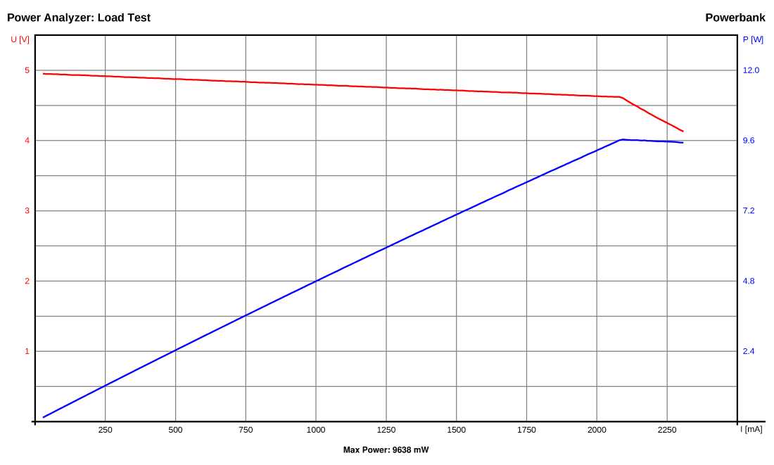
## **Load Test**

- Command: "l *maxloadcurrent[mA: 17..5000]* *minloadvoltage[mV: 0..26000]*"
- Example: "l 2500 4200"
- The Power Analyzer continuously increases the load from 17 mA up to *maxloadcurrent*. It stops automatically if the voltage drops below *minloadvoltage*. It continuously transmits the measured values via the serial interface in the format: current[mA] voltage[mV] power[mW] (seperated by the SEPERATOR string).
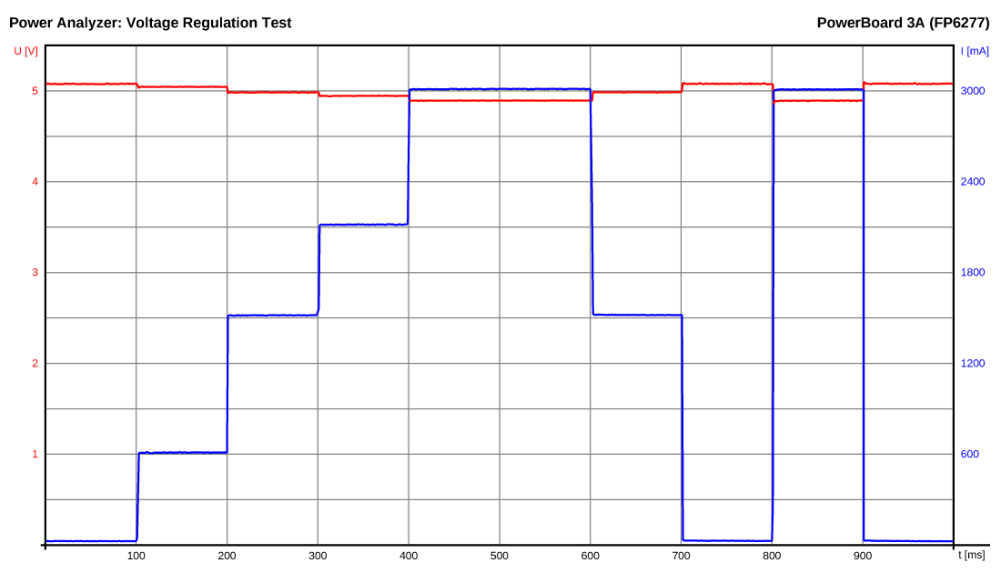
## **Voltage Regulation Test**
- Command: "g *maxloadcurrent[mA: 17..5000]*"
- Example: "g 3000"
- The Power Analyzer changes rapidly the load between 17 mA and *maxloadcurrent*. It continuously transmits the measured values via the serial interface in the format: time[ms] current[mA] voltage[mV] (seperated by the SEPERATOR string).
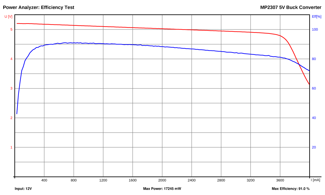
## **Efficiency Test**
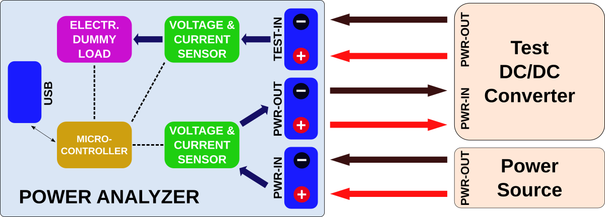
- Command: "e *maxloadcurrent[mA: 17..5000]* *minloadvoltage[mV: 0..26000]*"
- Example: "e 4000 2500"
- The Power Analyzer continuously increases the load from 17 mA up to *maxloadcurrent*. It stops automatically if the voltage at TEST-IN drops below *minloadvoltage*. It continuously transmits the measured values via the serial interface in the format: current[mA] voltage[mV] efficiency[% * 10] (seperated by the SEPERATOR string).
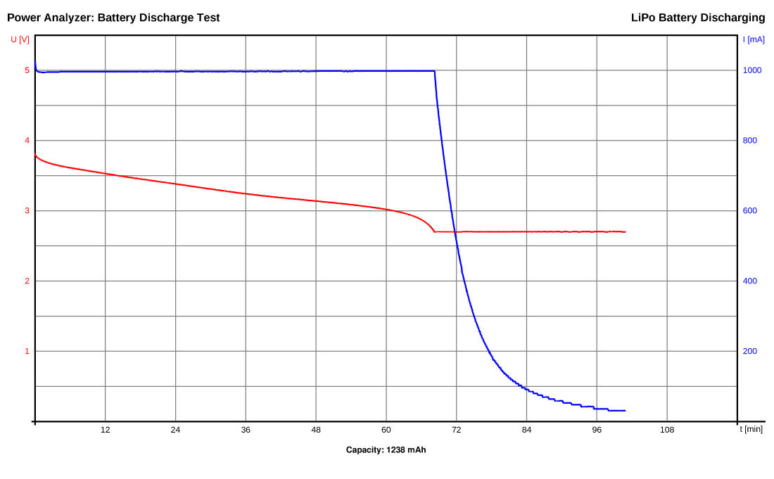
## **Battery Discharge Test**
- Command: "b *maxloadcurrent[mA: 17..5000]* *minloadvoltage[mV: 0..26000]*"
- Example: "l 1000 2700"
- The Power Analyzer sets a constant current load of *maxloadcurrent*. If the voltage drops below *minloadvoltage* it constantly decreases the load to maintain *minloadvoltage*. It stops automatically if the load current drops to 0mA. It continuously transmits the measured values via the serial interface in the format: time[s] current[mA] voltage[mV] capacity[mAh] (seperated by the SEPERATOR string).
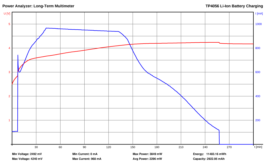
## **Long-Term Multimeter**

- Command: "m *interval[ms: 2..65535]* *duration[s: 1..65535]*"
- Example: "m 18000 18000"
- The Power Analyzer measures voltage, current and power delivered to the test device at every *interval* for a total of *duration*. It continuously transmits the measured values via the serial interface in the format: time[ms] current[mA] voltage[mV] (seperated by the SEPERATOR string).
## **Commands for Direct Control**
|Command|Function|
|-|-|
|"i"|transmits indentification string ("Power Analyzer")|
|"v"|transmits firmware version number|
|"x"|terminate current test program|
|"s *loadcurrent[mA]*"|set load to a constant current of *loadcurrent*|
|"r"|reset the load to minimum|
|"t"|read current and voltage of both sensors and transmit them|
# Notes
- Use a good heatsink with a 5V fan for the MOSFET! Attach a 10K 3950B NTC thermistor to the heatsink close to the MOSFET!
- Be careful with high power loads! Make some tests to figure out what can be achieved with your cooling solution!
- Due to the limitations of the cheap OpAmp and the internal DAC the minimum load current is around 17mA. You can choose a better OpAmp if you like (must have same pinout, must be rail-to-rail and unity gain stable), but for most cases this is not necessary.
- The maximum load current is 5A, however for small voltages it might be less.
- The maximum PWR-IN/PWR-OUT current is 8A.
- Do not exceed the maximum voltage of 26V on all connectors !
- In order to make the design much simpler all connectors including USB share a common ground. Keep this in mind when making your test setup in order to avoid ground loops or shorts. Using a [USB isolator](https://github.com/wagiminator/ADuM3160-USB-Isolator) between the Analyzer and your PC is not a bad idea!
- The CH330N can be replaced with a CH340N. Windows users may need to install a [driver](http://www.wch.cn/download/CH341SER_ZIP.html). This is not necessary for linux users.
- You need a UPDI programmer for uploading the firmware. You can find one in my [projects](https://github.com/wagiminator/AVR-Programmer) or you can easily build one following this [guide](https://github.com/SpenceKonde/AVR-Guidance/blob/master/UPDI/jtag2updi.md).
- The Python skript was only tested on Linux, but it should also work on other operating systems.
# License

This work is licensed under Creative Commons Attribution-ShareAlike 3.0 Unported License.
(http://creativecommons.org/licenses/by-sa/3.0/)
Design Drawing
schematic diagram
(
1
/
)
PCB
(
1
/
)
The preview image was not generated, please save it again in the
editor.
| ID | Name | Designator | Footprint | Quantity | BOM_Supplier | BOM_Supplier Part | BOM_Manufacturer Part |
|---|---|---|---|---|---|---|---|
| 1 | LMV321 | U3 | SOT-23-5_L3.0-W1.7-P0.95-LS2.8-BL | 1 | LCSC | C248567 | LMV321B-TR |
| 2 | CH330N | U2 | SOP-8_150MIL | 1 | LCSC | C108996 | CH330N |
| 3 | 1N4148W | D2 | DIODE-SOD-123 | 1 | LCSC | C241939 | 1N4148W-E3-08 |
| 4 | SI2302 | Q2 | SOT-23_L2.9-W1.3-P0.95-LS2.4-BR | 1 | LCSC | C344009 | SI2302 |
| 5 | KF301-2P | PWR-OUT,PWR-IN,TEST-IN | KF301-2P | 3 | LCSC | C474883 | KF301R-5.0-2P |
| 6 | USB-B-Female | USB | USB-M-49 | 1 | LCSC | C46393 | USB-B-Female-90-TH |
| 7 | 1k | R5,R6,R3,R2,R13,R4 | 0603 | 6 | LCSC | C21190 | 0603WAF1001T5E |
| 8 | 10k | R10,R14,R15 | 0603 | 3 | LCSC | C25804 | 0603WAF1002T5E |
| 9 | 1k5 | R16 | 0603 | 1 | LCSC | C22843 | 0603WAF1501T5E |
| 10 | 4k7 | R12,R1,R11 | 0603 | 3 | LCSC | C23162 | 0603WAF4701T5E |
| 11 | Header | UPDI | HDR-3X1/2.54 | 1 | LCSC | C49257 | Header2.54mm 1*3P |
| 12 | IRL540NPBF | Q1 | TO-220-3_L10.0-W4.5-P2.54-T | 1 | LCSC | C111607 | IRL540NPBF |
| 13 | ATTINY814-SSN | U1 | SOIC-14_150MIL | 1 | LCSC | C182202 | ATTINY814-SSNR |
| 14 | 1u | C5 | 0603 | 1 | LCSC | C15849 | CL10A105KB8NNNC |
| 15 | INA219 | U5,U4 | SOT-23-8 | 2 | LCSC | C87469 | INA219AIDCNR |
| 16 | Header | EXPANSION,I2C | HDR-4X1/2.54 | 2 | LCSC | C124413 | 220S-1*4P H=8.5MM Ytype Gold-plated |
| 17 | 100n | C4,C3,C9,C1,C10,C8,C6,C7 | 0603 | 8 | LCSC | C14663 | CC0603KRX7R9BB104 |
| 18 | 47u | C2 | 1206 | 1 | LCSC | C30300 | 1206F476M160NT |
| 19 | LED | RDY,PWR,BUSY | LED-0603 | 3 | LCSC | C72041 | 19-217/BHC-ZL1M2RY/3T |
| 20 | Header | NTC,FAN | HEADER_2X1 | 2 | LCSC | C86471 | 826629-2 |
| 21 | R300 | R7,R8,R9 | 2512 | 3 | LCSC | C176052 | CR2512F0R3E04 |
| 22 | R008 | R17,R18 | 2512 | 2 | LCSC | C76241 | MRF6432(2512)LR008FTS |
| 23 | SS54 | D1 | DIODE-SMA(DO-214AC) | 1 | LCSC | C123946 | SS54 |
Unfold
Project Members


 12
12
 28
28
Collect to album
Target complaint
Related Projects
Change a batch
Loading...
Add to album
×
Loading...
reminder
×
Do you need to add this project to the album?