
After Simulation, I got this Error on every Switch, could somebody help me to get rid of it?
@flotschinator98,
You link to the public project works OK.
Unfortunately, your simulation will not and after a quick look through your schematic, neither will the real circuit.
Your simulation will not work because it is built using symbols that have no spice model associated with them.
To correct this you must read - and play with the examples in - the Spice Tutorial, (3) in (2) in:
[https://easyeda.com/forum/topic/How-to-ask-for-help-and-get-an-answer-71b17a40d15442349eaecbfae083e46a](https://easyeda.com/forum/topic/How-to-ask-for-help-and-get-an-answer-71b17a40d15442349eaecbfae083e46a)<br>
<br>
You should be aware that, except for the THAT300 series transistor arrays, THAT Corp do not supply spice models for their devices. It may be possible to develop behavioural models in a similar way to that developed for EasyEDA for the V2164 quad VCA but that is a chargeable service that I provide separately from supporting EasyEDA. If you are interested in following this up please contact me via signality.co.uk.
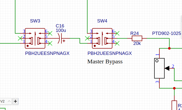
One of the reasons that your schematic will not work as a real circuit is because you have wired the switches, SW1 - SW4 incorrectly. There is no possoble connection between any of pins 1-3 and pins 4 - 6 in these switches:
Although probably not necessary in a simulation, your real circuit will need decoupling capacitance adding to each device supply pin in accordance with the manufacturer's datasheet recommendations.
Hi Andy, thank u for your support. I really appreciated your help.
I dont really understand what do u mean with "
It may be possible to develop behavioural models in a similar way to that developed for EasyEDA for the V2164 quad VCA". Instead of using the Bipolar Transistors That300, I should replace them with the V2164? Ths would be an good idead, so i save spaceon the PCB. What du you mean with the chargeable service?
According the decoupling capacitors, which dimension would be practical? In the Datasheet of the 4305 and
MC33078P, i coundnt find any other decoupling caps on the device supply pin as I used in my schematic. Maybe u could get me to get an idea where I can find that.
@flotschinator98,
There are two basic ways to make simulation models for devices in spice.
1. Transistor level models where the individual devices, transistors, diodes, RLC parts, of the real device are modelled individually using dedicated transistor, diode and RLC models. These run slowly because they are very detailed but if the models are created by the chip manufacturer they can be very accurate. However the fact that the models are from the manufacturer reveals a lot about their semiconductor fabrication processes so many manufacturers are very reluctant to release unencrypted models at this level.
2. Behvavioural models where the detailed operation of the device is represented by carefully crafted mathematical functions and expressions representing functional blocks of varying sizes within the device. This type of model can still contain device level elements for things like input and output capacitances and resistances or representing the dominant pole in an operational amplifier but they may contain no other models of realistic devices. For example the model of the V2164 that I created for EasyEDA boiled the operation of the device into a couple of mathematical functions with a few device level models for internal capacitances and some current sources for quiescent and operating supply currents. The EasyEDA operational amplifier models and 74H and 4000 series logic device models are all created that way.
The only reason I mentioned the THAT300 is because as far as I know, that is the only device for which THAT Corp supply a spice model. You have called up the THAT1256, THAT1646 and the THAT4305 for which there are no manufacturer supplied models available.
There is also no model for the DIYRECOLOUR module (which is very poorly documented anyway).
Models for the NE5534 and MC33072P are available and the switches can be represented as simple behavioural switch models using the basic spice SW model.
It is possible to develop behavioural models for the THAT1256, THAT1646 and THAT4305 but the DIYRECOLOUR module is more problematic because it is so poorly documented.
I could do this but not for free. If you would like to follow this up, please contact me through signality.co.uk.
Our website uses essential cookies to help us ensure that it is working as expected, and uses optional analytics cookies to offer you a better browsing experience. To find out more, read our Cookie Notice


 Brand new interactions and interfaces.


 Easy to use and quick to get started.