

<span class="colour" style="color: rgb(0, 0, 0);">Good evening, I am doing a project in which I want to measure air quality. I started the project with the ESP8266 NodeMcu board and three sensors, temperature (DHT22), VOC's (CCS811) and PM (PPD42).</span><br>
<br>
<span class="colour" style="color: rgb(0, 0, 0);">I have it all assembled with a breadboard and the NodeMcu and it works fine.</span><br>
<br>
<span class="colour" style="color: rgb(0, 0, 0);">The fact is that I want to pass it to PCB and I am a little lost. From what I've been reading, I have to use the same board but without NodeMcu, so I use ESP12-E.</span><br>
<br>
<span class="colour" style="color: rgb(0, 0, 0);">I have tried to make a design</span><span class="colour" style="color: rgb(0, 0, 0);">, (I attach images). I copied the connections that I already have working on the NodeMcu and grouped all the GND connections in a single point.</span><br>
<br>
<span class="colour" style="color: rgb(0, 0, 0);">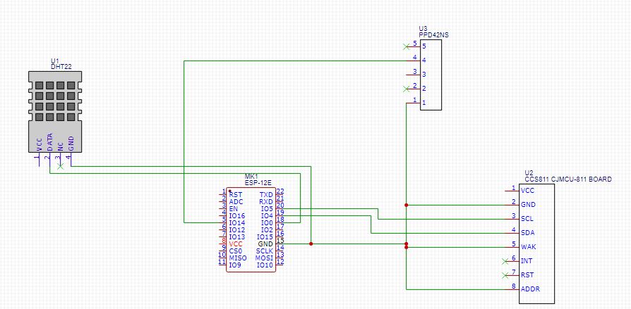</span><br>
<br>
<span class="colour" style="color: rgb(0, 0, 0);">The 3V3 pins I still have no idea how to do it, if anyone can give me a hand I would appreciate it.</span><br>
<br>
Also I do not know if the connections are good, since the NodeMcu has several components and I do not know if I have to put them here too, I am very new, if someone could confirm that the connection is correct I appreciate it.<span class="colour" style="color: rgb(0, 0, 0);"></span><br>
<br>
<span class="colour" style="color: rgb(0, 0, 0);">Am I wrong or am I on the right track?</span><br>
<br>
<span class="colour" style="color: rgb(0, 0, 0);">Thanks a lot! (::</span>


 Brand new interactions and interfaces.


 Easy to use and quick to get started.