Hi,
I'm getting a via diameter DRC error but there is no error. It says my via diameters are less than the DRC diameters but both are set to 0.61mm.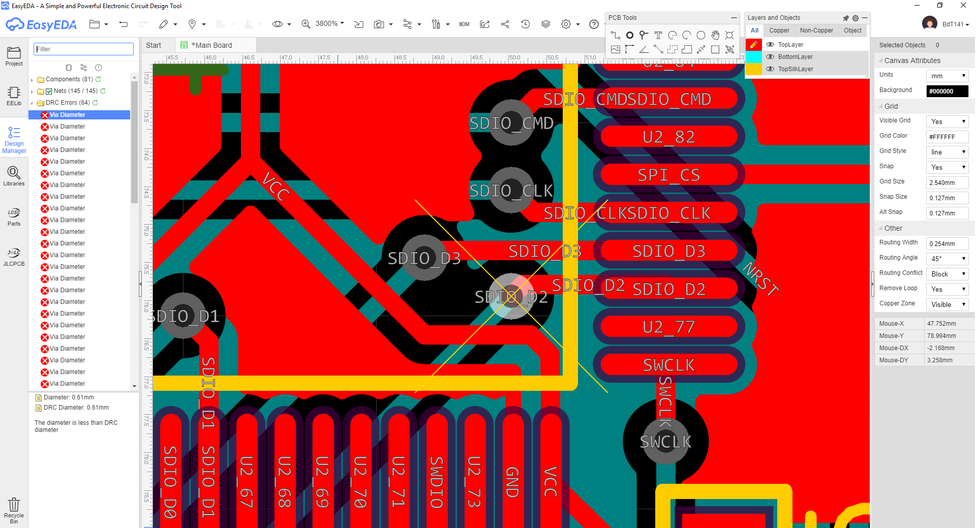
To me this is a huge issue.
I've been working on a PCB for a couple of weeks and always did DRC checks whenever I've completed some sub area. They were always OK and I had no DRC errors.
Now, suddenly, for whatever reason, it shows up with like 400 DRC errors.
Either there are DRC errors, or there are no DRC errors, it can not be that the application suddenly decides that there should be DRC errors.
Then when setting up design rules I enter "0.61" as the via diameter. All my vias are 0.61mm in diameter. It simply can not be that this would cause DRC errors.
How do I fix this? By going through 400+ vias in "mil" setting and adding an additional 0.016mil? Definitely not. This shouldn't be a problem in the first place and I need to know how this can be solved without having to edit 400+ vias!
@longoon12000 - Change the design rule, not your vias!. Just go into your Design Rule... settings and lower the via diameter and drill sizes by a fraction (for example, .6mm and .304mm) such that they are slightly smaller than whatever you already placed on your board. Your vias will then nicely exceed the minimum and all the errors will go away.
Other big issues here?
1) a new user on a new design will get errors by default and need to search the forums?
2) I think the router simply refused to route without this change (simply hung or failed to complete on a simple design -- one that needed via to complete though)
3) No statement has been made that a .609mm via will fabricate correctly... I sure hope so
Suggestions:
1) make the default rule a .609mm via -- so errors are avoided (assuming it will manufacture)
2) change the error message to include ("Known issue".... see \ )
Thoughts?
A new user will always have problems if they don't read the pinned topics in the forum and the instruction manual.
The DRC isn't some magic. YOU have to set it up for your project and the capabilities of your PCB manufacturer. If you are going to use JLC PCB, then here they are:
[https://jlcpcb.com/capabilities/Capabilities](https://jlcpcb.com/capabilities/Capabilities)
Also, never use the smallest track widths, distances etc or holes for your design unless you absolutely have to. If even a slight misalignment occurs during manufacturing, your boards are trash, because you were riding on the edge.
The defaults have always worked for me. YOU have to make sure your vias and everything else has the desired hole and pad sizes.
The autorouter is something you shouldn't use at all, especially if you are new to PCB design. If you don't know what's going on the PCB and component placement hasn't been thought abut, how will a point to point connector algorithm know what you want to do and what the PCB is supposed to do?
If you are going to use the autorouter, don't let it route the GND net. Add it to the skipped nets. Add a copper plane to both layers, top and bottom(for 2 layer boards) and add stitching vias to connect them.
If EASYEDA wants a very simple way of improving their product. If you are on metric system. Change the default DRC automatically. The product will be better. Dont even need to have a discussion on what you should or should not do.
@supermariusheier,
I can see how this works for a one-off change in units but does it still work if the user swaps units several times during a design incurring a rounding error in each swap?
The original problem isn't the value of the design rule or knowing which via diameters to use for which fabrication house. The problem is when you switch between mm and mil during the course of your layout the design rules does that imperial to metric conversion and gets it wrong because there are rounding errors. In my opinion the design rules shouldn't update every time you switch units of measure. I think their units should be kept separate. I switch between mm and mil often when I need exact distances between holes for example and then there are 100s of DRC errors.
Our website uses essential cookies to help us ensure that it is working as expected, and uses optional analytics cookies to offer you a better browsing experience. To find out more, read our Cookie Notice


 Brand new interactions and interfaces.


 Easy to use and quick to get started.