I notice when I drag components, the wires don't stretch/compress with that action. If I move a component I have to edit all the lines. Is it possible to drag all?
It is difficult to explain or even show in a video but wires in EasyEDA schematics drag, shorten and lengthen horizontally and vertically but any joins in a wire can become end points if the original end point of a wire moves such that the joint is left as the new end point of the wire.
How the wires drag depends on if you are moving:
1. a single schematic symbol selected by left-click-and-drag on the symbol;
2. a group of symbols and wires selected using the left-click-and-drag-a-rectangle then moved by left-clicking on any highlighted object;
3. a group of symbols and wires selected using the right-click-and-drag-a-rectangle then moved by left-clicking on any highlighted object.
The best thing to do is to make a simple schematic and then play with it to get used to how these different selections behave.
For more please see Basic Skills in the Tutorial.
Some components drag the wires, others don't. I have an Arduino UNO and some transistors that drag the wires as I move them. But three parts that have bus entries do not. If I drag the part to reposition it, the bus entries stay fixed. I really don't want to move 24 little wires every time I move the components. I made the bus entries using the bus-entry tool and the bus using the bus tool.
My schematic was private but I tried to make it public so you guys out there could see what I'm talking about, but I couldn't change it.
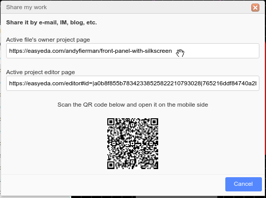
The simplest way to make a project public is to right click on it in the left hand panel then select Share, follow the instructions then copy and paste the link to the project.
Okay I think I shared it becuase when I try to edit, it shows it is public.
Project is Snowflake, white on black.
Share method was not as described. Share icon was on top banner, no need to click on left side.
There are several ways to set up sharing.
As a courtesy to people who are trying to help you and requested, please post the URL to the public project page like this:
The problem you are describing arises as a consequence of your having connected the bus entry symbols directly to the device pins without using short wire links between the bus entry/exit symbols and the pins and without applying any netlabels to them.
1. Without the short wires links, EasyEDA cannot rubber-band the connections because there is no wire there to stretch or shrink. The connections simply break apart.
2. Without netlabels the netlister has no way to know which pins are connected by the bus entry/exit symbols.
If you check the Nets and specific pins in the Design Manager, you will find that none of the pins that you want to connect by the bus are actually connected to any other pins.
To understand how to use the Bus/Entry/Exit symbols properly, please study this project:
[https://easyeda\.com/andyfierman/bus\_across\_2\_schematics\-64e86b65e3bd4e35afcc7f0e51f46d73](https://easyeda.com/andyfierman/bus_across_2_schematics-64e86b65e3bd4e35afcc7f0e51f46d73)
Note that although the example is showing connections across two sheets, the same rules apply to bussed connections within a single sheet schematic such as yours.
@queenidog,
Even if the connection break is fixed in v6.2, you still **must** attach net labels to **all** the nets that you want to be connected by a bus at **all** their entry and exit points to the bus.
This is because the bus symbols are just graphical symbols and the net labels are the only way that EasyEDA can understand how the pins connected to the bus entry and exit symbols are connected to each other.
DipTrace allows you to make a bus and when wires connect to the bus, the entry/exits (the /) are automatically applied. EasyEDA is too tedious in its implementation.
The bus entry symbols should not just be "graphical symbols", that's crazy for a schematic drawing (the only graphical symbol allowed should be outline.) I use Visio when I want to go graphical drawings.
There are other issues where DipTrace is better/faster/more intuitive, but overall I really like EasyEDA (libraries are FANTASTIC- DipTraces' suck!) and will continue to use it as new versions come out.
Our website uses essential cookies to help us ensure that it is working as expected, and uses optional analytics cookies to offer you a better browsing experience. To find out more, read our Cookie Notice


 Brand new interactions and interfaces.


 Easy to use and quick to get started.